REYES Options
REYES Options
- Introduction
- Hiders
- カメラ
- Displays
- レンダリング Options
- レンダリング
- Checkpointing
- Re-rendering
- Bucket Size
- Grid Size
- Hair Length
- Hair Width
- Curve Orientation
- Curve Cacheing
- Stochastic Transparency
- Arbitrary Bucket Order
- Threads
- Ray Tracing
- Pretessellation
- Off-Screen Strategy
- Photon
- Shade
- Visible Point (VP) Options
- Opacity Threshold
- Opacity Culling
- Shadow Maps
- テクスチャ フィルタリング
- Deep テクスチャ Compression
- Memory
- Statistics
- RIB Output
- RIB Authoring
- Search Paths
- Directory Mapping
- User Specified Options
Introduction
Every implementation of a RenderMan-compliant rendering program has certain implementation-specific features that are accessed through the functions RiAttribute and RiOption. Options are parameters that affect the rendering of an entire image. They must be set before calling RiWorldBegin, since at that point options for a specific frame are frozen.
The complete set of options includes: a description of the camera, which controls all aspects of the imaging process (including the camera position and the type of projection); a description of the display, which controls the output of pixels (including the types of images desired, how they are quantized and which device they are displayed on); as well as renderer run-time controls (such as the hidden surface algorithm to use).
This document describes the options available to control the operation of PRMan. Each section gives an example of the use of the option as it would appear in RenderMan Interface.
RiOption ( RtToken name, parameterlist )
Sets the named implementation-specific option. A rendering system may have certain options that must be set before the renderer is initialized. In this case, RiOption may be called before RiBegin to set those options only.
Although RiOption is intended to allow implementation-specific options, there are a number of options that we expect that nearly all implementations will need to support. It is intended that when identical functionality is required, that all implementations use the option names listed in the table below.
RIB BINDING
Option name ...parameterlist...
EXAMPLE
Option "limits" "gridsize" [32] "bucketsize" [12 12]
SEE ALSO
| Option name/param | Type | Default | Description |
|---|---|---|---|
| "searchpath" "archive" [s] | string | "" | List of directories to search for RIB archives. |
| "searchpath" "texture" [s] | string | "" | List of directories to search for texture files. |
| "searchpath" "shader" [s] | string | "" | List of directories to search for shaders. |
| "searchpath" "procedural" [s] | string | "" | List of directories to search for dynamically-loaded RiProcedural primitives. |
| "statistics" "endofframe" [i] | int | 0 | If nonzero, print runtime statistics when the frame is finished rendering. |
Hiders
PRMan supports the standard hiders required by RiHider as defined in the RenderMan specification: the null, paint, and hidden hiders, with the hidden hider actually being an alias for the stochastic hider. PRMan also supplies four additional hiders: the depthmask, photon, raytrace, and zbuffer hiders. The default hider, if none is specified, is the hidden (stochastic) hider.
RiHider ( RtToken type, ...parameterlist... )
RIB BINDING
Hider type parameterlist
EXAMPLE
RiHider "paint"
The following table summarizes each hider's support for various features in PRMan.
| Feature | paint | zbuffer | photon | depthmask | hidden | raytrace |
|---|---|---|---|---|---|---|
| Motion Blur | no | no | yes | yes | yes | yes |
| Transparency | no | no | yes | yes | yes | yes |
| Trim Curves | limited | limited | yes | yes | yes | yes |
| CSG | no | no | yes | yes | yes | yes |
| Depth of Field | no | no | no | yes | yes | yes |
| Jitter | no | no | no | yes | yes | yes |
| レンズ Aperture | no | no | no | yes | yes | yes |
| シャッター Opening | no | no | no | yes | yes | yes |
| Arbitrary Output | no | no | no | yes | yes | yes |
| Deep Output | no | no | no | yes | yes | yes |
| Arbitrary Clipping Plane | no | no | no | yes | yes | yes |
| Occlusion Culling | no | no | yes | yes | yes | no |
| Opacity Culling | no | no | no | yes | yes | yes |
| Matte | no | no | no | yes | yes | yes |
| PixelVariance | no | no | no | no | no | yes |
| Sigma | no | no | no | yes | yes | no |
| Point Falloff | no | no | no | yes | yes | no |
| Depth Masking | no | no | no | yes | no | no |
| Visible Point シェーディング | no | no | no | yes | yes | no |
Currently, there are three options that are supported by all PRMan hiders.
Subpixel Output
This option forces the hider to emit every subpixel into the final image, generating an image which is PixelSamples-times larger, but has every unfiltered color and depth available for perusal. For example, asking for a 640x480 image with PixelSamples 4x4, but with subpixel output, would generate a 2560x1920 unfiltered image.
Hider "stochastic" "int subpixel" [1]
Micropolygon Caching
PRMan supports micropolygon caching for dealing with large amounts of in-memory transient micropolygons: it will cache these transient micropolygons to disk when it is detected that there are a relatively large number of them. Several hider options control micropolygon caching. First, the "mpcache" option, when set to 1, enables the micropolygon caching strategy.
Hider "stochastic" "int mpcache" [1]
When the strategy is enabled, caching is activated once more than 6MB of transient micropolygons have been created. This can be controlled by the "mpmemory" option. Changing this number controls the number of KB of micropolygons that can be created before micropolygons begin to be cached to disk.
Cache files are written in the "mpcachedir" location under a directory named "mpc.hostname.n", where hostname is the the name of the host, and n is the process id of the prman process controlling the cache. The renderer will attempt to remove any orphaned cache directories left behind by other invocations of prman. If "mpcachedir" is not specified then the default directory will be the current one; this may be overridden by altering the /prman/hider/mpcachedir directive specified in rendermn.ini.
Maximum Visible Point Depth
The maxvpdepth option controls the maximum number of visible points considered for compositing or deep shadow map creation in the hider. By default, this hider option is disabled (set to -1), meaning that there is no limit on the number of visible points considered by the hider. Setting it to a number n forces the hider to trim visible point lists whenever they grow greater than n. This is useful for optimizing deep shadow maps in order to ensure that they have an upper bound on the length of the depth functions per pixel, and for keeping an upper bound on the memory consumed by visible point lists. Note that this option may have limited or no effect on any hider which does not output more than one visible point per subpixel (i.e. any hider which does not support transparency).
Raytrace Hider
The raytrace hider renders images using pure ray tracing, bypassing the usual rasterization process that PRMan uses. Rays are shot from the camera with jittered time samples and lens positions to produce accurate motion blur and depth of field effects.
Important
samplemode is deprecated as of PRMan 19 in both REYES- and RIS-mode. Setting PixelVariance to a non-zero value implies adaptive sampling, while setting it to zero implies fixed sampling.
Hider "raytrace" "string samplemode" ["fixed"] "int minsamples" [2]The samplemode option controls whether the raytrace hider shoots a fixed number of rays per pixel or not. If samplemode is fixed, the number of rays traced per pixel by the hider is determined by the PixelSamples setting. One camera ray will be traced for each pixel sample, and the number of rays per pixel will be uniform across the image.
If the samplemode is instead adaptive, the raytrace hider will trace a variable number of rays per pixel. At a maximum, it will trace as many camera rays per pixel as it would have in fixed mode. In smoother regions of the image, it may trace as few as one per pixel. The minsamples parameter may be used to increase this minimum. It should be raised if the adaptive sampling produces artifacts. The PixelVariance setting also affects adaptive sampling; reducing its value increases the likelihood that it will trace more rays while increasing its value allows more undersampling.
The raytrace hider supports the same lens aperture and anamorphic depth of field options as the stochastic hider. Likewise, it supports the sample samplemotion, jitter, and extrememotiondof options. Note, however, that jitter will always be applied when doing adaptive sampling.
PRMan 18 introduced three new (optional) parameters to the raytrace hider. "string integrationmode" ["distribution" | "path"] tells the raytrace hider whether to use distribution ray tracing or path tracing. The default is "distribution" (ray tracing).
Hider "raytrace" "string integrationmode" ["path"] "int maxsamples" [256] "int incremental" [1]
When integrationmode is set to "path" it does three things:
- Features that only makes sense when using distribution-style integration are automatically disabled (specifically, the radiosity cache is disabled).
- The renderer provides an option that can be queried by shaders to determine if the render is in "path" mode.
- The hider will iterate over the image, tracing one ray per pixel at each iteration until the maximum number of paths per pixel have been traced.
Each iteration will accumulate the result and update the display to show the results as they converge.
Note
Because it is required, "integrationmode" "path" is assumed in RIS mode; adding it is optional, and "integrationmode" "distribution" is ignored.
Additionally, the raytrace hider supports new "maxsamples" and "incremental" parameters (see the example above). "maxsamples" sets an explicit limit for the number of samples; it defaults to 0. The "incremental" parameter enables the progressive display of results (rather than bucketed results); it is off (0) by default. Note that, as of PRMan 19, minsamples defaults to the square root of the maxsamples setting.
When path tracing, Hider "raytrace" "int adaptall" [1] can be used to control channels that are considered by the adaptive sampler. The default, 1, indicates that all channels that use normal pixel filtering are considered when deciding if a pixel is converging. Setting it to 0 will restrict it to the RGBA beauty pass only and ignore AOVs.
Depthmask Hider
The depthmask hider is identical to the stochastic hider, except that instead of computing visibility at the image plane, the depthmask hider computes visibility at a frontier defined by depths in a shadow map. Hence, the depthmask hider supports the same options as the stochastic hider, along with three new parameters.
Hider "depthmask" "string zfile" ["shadowmap.sm"] "int reversesign" [0] "float depthbias" [0.01]
- The zfile option takes a shadow map file (created with txmake -shadow or RiMakeShadow) or a deep texture file. The hider will then cull surfaces that are nearer (or farther) than the frontier defined by the depth values.
- The parameter reversesign controls whether z-depths greater than or less than the depth mask are culled. The default value of 0 culls all geometry in front of the depth mask. Setting this parameter to 1 allows the depth mask to be used to cull geometry behind the mask.
- The parameter depthbias controls the amount of bias applied to the mask. The default for this parameter is 0.01. Raising this value will prevent self-intersection problems in cases where two surfaces are extremely close.
Note
The shadowmap passed to the depthmask hider must be at sample resolution (see subpixel output above). This means the width of the shadow map must be the width of the image being produced by the hider times the x-component of PixelSamples. Similarly, the height of the shadow map must be the height of the image being produced by the hider times the y-component of PixelSamples. If these conditions are not met, the result is undefined.
Null Hider
The null hider performs no visibility computations whatsoever. Any images produced by the renderer using this hider will be empty. (Image outputs can themselves be disabled by using the null display driver.)
Paint Hider
The paint hider renders objects directly into a frame buffer in back to front order without using a z-buffer. (Note that this is counter to the specification; objects are not rendered in the order specified, but are sorted by depth first.) Motion blur, transparency, depth of field, arbitrary output variables, arbitrary clipping planes, level of detail, CSG, matte objects, deep shadow output, and visible point shading are not supported by this hider. This hider does not have any specific options other than those supported by all other hiders.
Photon Hider
The photon hider controls the generation of photon maps. Hider "photon" "int emit" [100000] puts the renderer into photon map calculation mode. Photon map generation is a separate rendering pass, akin to shadow map generation, so photon map generation begins when RiWorldEnd is encountered and the Hider is set to "photon". Photons are tagged as global and/or caustic. Caustic photons are deposited into an optional caustic photon map and are specially tuned for use in calculating caustic effects. Global photons are deposited into the optional global photon map and are used to calculate soft indirect illumination. You can generate either or both types of photon maps in a single rendering pass, but if you need very high quality caustics, you'll probably want to increase the photon emission and compute them in a separate photon pass. A single photon pass can result in any number of photon map files. When a photon is "deposited" at a surface point, the standard photon map attributes are consulted to determine the name of the photon map file. To prevent the deposition of a photon on a specific object, specify the empty string for the photon map name.
Z-Buffer Hider
The z-buffer hider renders objects directly into a frame buffer in back-to-front order, using a pixelsample-sized z-buffer to resolve hidden surface elimination. Motion blur, transparency, depth of field, arbitrary output variables, arbitrary clipping planes, level of detail, CSG, matte objects, deep shadow output, and visible point shading are not supported by this hider. This hider does not have any specific options other than those supported by all other hiders.
カメラ
The graphics state contains a set of parameters that define the properties of the camera. The complete set of camera options is described in the table below.
The viewing transformation specifies the coordinate transformations involved with imaging the scene onto an image plane and sampling that image at integer locations to form a raster of pixel values. A few of these procedures set display parameters such as resolution and pixel aspect ratio. If the rendering program is designed to output to a particular display device these parameters are initialized in advance. Explicitly setting these makes the specification of an image more device dependent and should only be used if necessary. The defaults given in the カメラ Options table characterize a hypothetical framebuffer and are the defaults for picture files.
| カメラ Option | Type | Default | Description |
|---|---|---|---|
| Horizontal Resolution | integer | 640 [1] | The horizontal resolution in the output image. |
| Vertical Resolution | integer | 480 [1] | The vertical resolution in the output image. |
| Pixel Aspect Ratio | float | 1.0 [1] | The ratio of the width to the height of a single pixel. |
| Crop Window | 4 floats | (0,1,0,1) | The region of the raster that is actually rendered. |
| Frame Aspect Ratio | float | 4/3 [1] | The aspect ratio of the desired image. |
| Screen Window | 4 floats | (-4/3,4/3,-1,1) [1] | The screen coordinates (coordinates after the projection) of the area to be rendered. |
| カメラ Projection | token | "orthographic" | The camera to screen projection. |
| World to カメラ | transform | identity | The world to camera transformation. |
| Clipping Planes | 2 floats | (epsilon, infinity) | The positions of the near and far clipping planes. |
| Other Clipping Planes | list of planes | n/a | Additional planes that clip geometry from the scene. |
f-Stop
Focal Length
Focal Distance
|
float
float
float
|
infinity
n/a
n/a
|
Parameters controlling depth of field. |
シャッター Open
シャッター Close
|
float
float
|
0
0
|
The times when the shutter opens and closes. |
| [1] | (1, 2, 3, 4, 5) Interrelated defaults |
The camera model supports near and far clipping planes that are perpendicular to the viewing direction, as well as any number of arbitrary user-specified clipping planes. Depth of field is specified by setting an f-stop, focal length, and focal distance just as in a real camera. Objects located at the focal distance will be sharp and in focus while other objects will be out of focus. The shutter is specified by giving opening and closing times. Moving objects will blur while the camera shutter is open.
The imaging transformation proceeds in several stages. Geometric primitives are specified in the object coordinate system. This canonical coordinate system is the one in which the object is most naturally described. The object coordinates are converted to the world coordinate system by a sequence of modeling transformations. The world coordinate system is converted to the camera coordinate system by the camera transformation. Once in camera coordinates, points are projected onto the image plane or screen coordinate system by the projection and its following screen transformation. Points on the screen are finally mapped to a device dependent, integer coordinate system in which the image is sampled. This is referred to as the raster coordinate system and this transformation is referred to as the raster transformation. These various coordinate systems are summarized in the table below:
| Coordinate System | Description |
|---|---|
| "object" | The coordinate system in which the current geometric primitive is defined. The modeling transformation converts from object coordinates to world coordinates. |
| "world" | The standard reference coordinate system. The camera transformation converts from world coordinates to camera coordinates. |
| "camera" | A coordinate system with the vantage point at the origin and the direction of view along the positive z-axis. The projection and screen transformation convert from camera coordinates to screen coordinates. |
| "screen" | The 2D normalized coordinate system corresponding to the image plane. The raster transformation converts to raster coordinates. |
| "raster" | The raster or pixel coordinate system. An area of 1 in this coordinate system corresponds to the area of a single pixel. This coordinate system is either inherited from the display or set by selecting the resolution of the image desired. |
| "NDC" | Normalized device coordinates - like "raster" space, but normalized so that x and y both run from 0 to 1 across the whole (un-cropped) image, with (0,0) being at the upper left of the image, and (1,1) being at the lower right (regardless of the actual aspect ratio). |
These various coordinate systems are established by camera and transformation commands. The order in which camera parameters are set is the opposite of the order in which the imaging process was described above. When RiBegin is executed it establishes a complete set of defaults. If the rendering program is designed to produce pictures for a particular piece of hardware, display parameters associated with that piece of hardware are used. If the rendering program is designed to produce picture files, the parameters are set to generate a video-size image. If these are not sufficient, the resolution and pixel aspect ratio can be set to generate a picture for any display device. RiBegin also establishes default screen and camera coordinate systems as well. The default projection is orthographic and the screen coordinates assigned to the display are roughly between +/- 1.0. The initial camera coordinate system is mapped onto the display such that the +x axis points right, the +y axis points up, and the +z axis points inward, perpendicular to the display surface. Note that this is left-handed.
Before any transformation commands are made, the current transformation matrix contains the identity matrix as the screen transformation. Usually the first transformation command is an RiProjection, which appends the projection matrix onto the screen transformation, saves it, and reinitializes the current transformation matrix as the identity camera transformation. This marks the current coordinate system as the camera coordinate system. After the camera coordinate system is established, future transformations move the world coordinate system relative to the camera coordinate system. When an RiWorldBegin is executed, the current transformation matrix is saved as the camera transformation, and thus the world coordinate system is established. Subsequent transformations inside of an RiWorldBegin-RiWorldEnd establish different object coordinate systems.
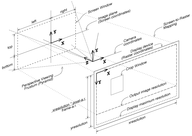
カメラ-to-Raster Projection ジオメトリ
The following example shows how to position a camera:
RiBegin();
   RiFormat( xres, yres, 1.0 );   /*Raster coordinate system*/
   RiFrameAspectRatio( 4.0/3.0 ); /*Screen coordinate system*/
   RiFrameBegin(0);
      RiProjection("perspective,"...); /*カメラ coordinate system*/
      RiRotate(... );
      RiWorldBegin();      /*World coordinate system*/
      ...
         RiTransform(...);   /*Object coordinate system*/
      RiWorldEnd();
   RiFrameEnd();
RiEnd();
The various camera procedures are described below, with some of the concepts illustrated above.
Riカメラ (RtToken name, ...parameterlist... )
This function marks the camera description from the current graphics state options, and saves it using name. This camera description can then be referred to by name in subsequent calls to RiAttribute or RiDisplay. The camera description that is saved includes:
- the screen window (set by RiScreenWindow);
- the image dimension (set by RiFormat and RiFrameAspectRatio);
- the camera projection (set by RiProjection);
- the depth of field settings (set by RiDepthOfField);
- the clipping planes (set by RiClipping); and
- the world to camera transformation.
The camera description which is created is itself an option (i.e. part of the global state). Hence, Riカメラ is valid only before RiWorldBegin.
Riカメラ also creates a marked coordinate system with the same name (similar to RiCoordinateSystem). This coordinate system can then be referred to by name in subsequent shaders, or in RiTransformPoints.
The renderer will automatically create two special camera definitions if they do not already exist: the current camera definition at RiFrameBegin is named "frame", and the current camera definition at RiWorldBegin is named "world". Users are allowed to explicitly instantiate these camera definitions prior to RiFrameBegin and RiWorldBegin respectively, in order to specify camera parameters that cannot be otherwise represented by a separate Ri function call. Since the world to camera transformation is explicitly saved with the camera description, this means that the world coordinate system for rendering will actually be the coordinate system saved with the "world" camera, and not the coordinate system in effect at the time of RiWorldBegin.
- Depth of Field
The depthoffield option exposes the same lens parameters as RiDepthOfField
RtInt dof[3] = {22, 45, 1200};
Riカメラ("world", "float[3] depthoffield", (RtPointer)dof, RI_NULL);
- Extreme Offset
By default, multi-camera rendering assumes that the separation between cameras is small. This allows for several optimizations that lead to faster rendering, but may lead to bucket artifacts if the separation between cameras is large. Setting the "extremeoffset" parameter to 1 will remove this assumption and fix these bucket artifacts, but may lead to slower renderings.
RtInt w = 1;
Riカメラ("lefteye", "int extremeoffset", (RtPointer)&w, RI_NULL);
For more information on multi-camera rendering, please consult the application note.
- Focus Region
The focusregion option is an extension to depth of field allowing a range in depth to be kept in focus, rather than just one discrete depth. This works with either RiDepthOfField or the Riカメラ "depthoffield" option.
RtInt w = 12;
Riカメラ("world", "float focusregion", (RtPointer)&w, RI_NULL);
- シャッター Opening
The shutteropening option allows control over the speed with which the shutter opens and closes. The float[2] shutteropening Riカメラ parameter replaces the RiHider shutteropening option. Its two arguments, a and b, are fractions of the shutter interval specified in Riシャッター. Over the first part of the shutter interval, from 0 to a, the shutter gradually admits more light; from a to b it is fully open; and from b to 1 it gradually closes. The rate of opening and closing is constant.
Riカメラ also supports a float[10] shutteropening version of the parameter, which enables a non-constant rate of opening and closing. It adds eight more arguments, c1, c2, d1, d2, e1, e2, f1, and f2. The two points (c1,c2) and (d1,d2) specify the rate of the shutter opening motion as control points of a bezier curve between (0,0) and (a,1). Likewise, (e1,e2) and (f1,f2) specify the shutter closing as a bezier curve between (b,1) and (1,0). More detail is available in the Advanced カメラ Modeling application note.
If the "shutteropening" option is not specified, the default "float[2] shutteropening" [0 1] is used, resulting in instantaneous open/close timing.
RtFloat so_linear[2] = {0.4, 0.6};
Riカメラ("world", "float[2] shutteropening", (RtPointer)so_linear, RI_NULL);

RtFloat so_bezier[10] = {0.4, 0.6, 0.1, 0.1, 0.3, 0.2, 0.6, 0.2, 0.9, 0.1};
Riカメラ("world", "float[10] shutteropening", (RtPointer)so_bezier, RI_NULL);
RIB BINDING
カメラ name ...parameterlist...
EXAMPLE
カメラ "rightcamera"
RiFormat ( RtInt xresolution, RtInt yresolution, RtFloat pixelaspectratio )
Set the horizontal (xresolution) and vertical (yresolution) resolution (in pixels) of the image to be rendered. The upper left hand corner of the image has coordinates (0,0) and the lower right hand corner of the image has coordinates (xresolution, yresolution). If the resolution is greater than the maximum resolution of the device, the desired image is clipped to the device boundaries (rather than being shrunk to fit inside the device). This command also sets the pixel aspect ratio. The pixel aspect ratio is the ratio of the physical width to the height of a single pixel. The pixel aspect ratio should normally be set to 1 unless a picture is being computed specifically for a display device with non-square pixels.
Implicit in this command is the creation of a display viewport with a
The viewport aspect ratio is the ratio of the physical width to the height of the entire image.
An image of the desired aspect ratio can be specified in a device independent way using the procedure RiFrameAspectRatio described below. The RiFormat command should only be used when an image of a specified resolution is needed or an image file is being created.
If this command is not given, the resolution defaults to that of the display device being used. Also, if xresolution, yresolution, or pixelaspectratio is specified as a nonpositive value, the resolution defaults to that of the display device for that particular parameter.
RIB BINDING
Format xresolution yresolution pixelaspectratio
EXAMPLE
Format 512 512 1
SEE ALSO
RiFrameAspectRatio ( RtFloat frameaspectratio )
RiFrameAspectRatio is the ratio of the width to the height of the desired image. The picture produced is adjusted in size so that it fits into the display area specified with RiDisplay or RiFormat with the specified frame aspect ratio and is such that the upper left corner is aligned with the upper left corner of the display.
If this procedure is not called, the frame aspect ratio defaults to that determined from the resolution and pixel aspect ratio.
RIB BINDING
FrameAspectRatio frameaspectratio
EXAMPLE
RiFrameAspectRatio (4.0/3.0);
SEE ALSO
RiScreenWindow ( RtFloat left, RtFloat right, RtFloat bottom, RtFloat top )
This procedure defines a rectangle in the image plane that gets mapped to the raster coordinate system and that corresponds to the display area selected. The rectangle specified is in the screen coordinate system. The values left, right, bottom, and top are mapped to the respective edges of the display.
The default values for the screen window coordinates are:
(-frameaspectratio, frameaspectratio, -1, 1)
if frameaspectratio is greater than or equal to one, or:
(-1, 1, -1/frameaspectratio, 1/frameaspectratio)
if frameaspectratio is less than or equal to one. For perspective projections, this default gives a centered image with the smaller of the horizontal and vertical fields of view equal to the field of view specified with RiProjection. Note that if the camera transformation preserves relative x and y distances, and if the ratio
is not the same as the frame aspect ratio of the display area, the displayed image will be distorted.
RIB BINDING
ScreenWindow left right bottom top
ScreenWindow [left right bottom top]
EXAMPLE
ScreenWindow -1 1 -1 1
SEE ALSO
RiCropWindow ( RtFloat xmin, RtFloat xmax, RtFloat ymin, RtFloat ymax )
Render only a sub-rectangle of the image. This command does not affect the mapping from screen to raster coordinates. This command is used to facilitate debugging regions of an image, and to help in generating panels of a larger image. These values are specified as fractions of the raster window defined by RiFormat and RiFrameAspectRatio, and therefore lie between 0 and 1. By default the entire raster window is rendered. The integer image locations corresponding to these limits are given by:
rxmin = clamp (ceil ( xresolution*xmin ), 0, xresolution-1);
rxmax = clamp (ceil ( xresolution*xmax -1 ), 0, xresolution-1);
rymin = clamp (ceil ( yresolution*ymin ),  0, yresolution-1);
rymax = clamp (ceil ( yresolution*ymax -1 ), 0, yresolution-1);
These regions are defined so that if a large image is generated with tiles of abutting but non-overlapping crop windows, the subimages produced will tile the display with abutting and non-overlapping regions.
RIB BINDING
CropWindow xmin xmax ymin ymax
CropWindow [xmin xmax ymin ymax]
EXAMPLE
RiCropWindow (0.0, 0.3, 0.0, 0.5);
SEE ALSO
RiProjection ( RtToken name, ... parameterlist ... )
The projection determines how camera coordinates are converted to screen coordinates, using the type of projection and the near/far clipping planes to generate a projection matrix. It appends this projection matrix to the current transformation matrix and stores this as the screen transformation, then marks the current coordinate system as the camera coordinate system and reinitializes the current transformation matrix to the identity camera transformation. The required types of projection are "perspective", "orthographic, and RI_NULL.
"perspective" builds a projection matrix that does a perspective projection along the z-axis, using the RiClipping values, so that points on the near clipping plane project to z=0 and points on the far clipping plane project to z=1. "perspective" takes one optional parameter, "fov", a single RtFloat that indicates the full angle perspective field of view (in degrees) between screen space coordinates (-1,0) and (1,0) (equivalently between (0,-1) and (0,1)). The default is 90 degrees.
Note that there is a redundancy in the focal length implied by this procedure and the one set by RiDepthOfField. The focal length implied by this command is:
"orthographic" builds a simple orthographic projection that scales z using the RiClipping values as above. "orthographic" takes no parameters.
RI_NULL uses an identity projection matrix, and simply marks camera space in situations where the user has generated his own projection matrices himself using RiPerspective or RiTransform.
This command can also be used to select implementation-specific projections or special projections written in the シェーディング Language. If a particular implementation does not support the special projection specified, it is ignored and an orthographic projection is used. If RiProjection is not called, the screen transformation defaults to the identity matrix, so screen space and camera space are identical.
PRMan 19 introduced three new built-in projections: "sphere", "torus", and "cylinder". Rather than the usual projection through an image plane, these trace rays through curved surfaces centered on the viewpoint. The parameters for these projections and their defaults are as follows:
Projection "sphere" "float hsweep" [360] "float vsweep" [180]
Projection "torus" "float hsweep" [360] "float vsweep" [180] "float minor" [0.25]
Projection "cylinder" "float hsweep" [360]
In each case, the hsweep and vsweep parameters give the angle range to be covered by the -1 to 1 span in screen window coordinates. By default these ranges will be covered exactly by square images; wider or taller images will cover a larger sweep in one direction or the other. This default can be altered with RiScreenWindow.
For the torus projection, the minor parameter is the ratio of the minor radius to the major radius.
Note that these may interact poorly with the standard frustum oriented dicing strategies. As a result, the following settings are recommended for use with these projections:
Attribute "dice" "int rasterorient" [0]
                 "string strategy" ["sphericalprojection"]
                 "string offscreenstrategy" ["sphericalprojection"]
These projections are compatible with all modes of the raytrace hider.
RIB BINDING
Projection "perspective" ...parameterlist...
Projection "orthographic"
Projection name ...parameterlist...
EXAMPLE
RiProjection (RI_ORTHOGRAPHIC, "fov", &fov, RI_NULL);
SEE ALSO
RiClipping ( RtFloat near, RtFloat far )
Sets the position of the near and far clipping planes along the direction of view. near and far must both be positive numbers. near must be greater than or equal to RI_EPSILON and less than far. far must be greater than near and may be equal to RI_INFINITY. These values are used by RiProjection to generate a screen projection such that depth values are scaled to equal zero at z=near and one at z=far. Notice that the rendering system will actually clip geometry that lies outside of z=(0,1) in the screen coordinate system, so non-identity screen transforms may affect which objects are actually clipped.
For reasons of efficiency, it is generally a good idea to bound the scene tightly with the near and far clipping planes.
RIB BINDING
Clipping near far
EXAMPLE
Clipping .1 10000
SEE ALSO
RiClippingPlane ( RtFloat nx, RtFloat ny, RtFloat nz, RtFloat x, RtFloat y, RtFloat z)
Adds a user-specified clipping plane. The plane is specified by giving the normal, (nx, ny, nz), and any point on its surface, (x, y, z). All geometry on the negative side of the plane (that is, opposite the direction that the normal points) will be clipped from the scene. The point and normal parameters are interpreted as being in the active local coordinate system at the time that the RiClippingPlane statement is issued.
Multiple calls to RiClippingPlane will establish multiple clipping planes.
RIB BINDING
ClippingPlane nx ny nz x y z
EXAMPLE
ClippingPlane 0 0 -1 3 0 0
SEE ALSO
RiDepthOfField ( RtFloat fstop, RtFloat focallength, RtFloat focaldistance )
focaldistance sets the distance along the direction of view at which objects will be in focus. focallength sets the focal length of the camera. These two parameters should have the units of distance along the view direction in camera coordinates. fstop, or aperture number, determines the lens diameter:
If fstop is RI_INFINITY, a pin-hole camera is used and depth of field is effectively turned off. If the Depth of Field capability is not supported by a particular implementation, a pin-hole camera model is always used.
If depth of field is turned on, points at a particular depth will not image to a single point on the view plane but rather a circle. This circle is called the circle of confusion. The diameter of this circle is equal to

Note that there is a redundancy in the focal length as specified in this procedure and the one implied by RiProjection.
RIB BINDING
DepthOfField fstop focallength focaldistance
DepthOfField -
The second form specifies a pin-hole camera with infinite fstop, for which the focallength and focaldistance parameters are meaningless.
EXAMPLE
DepthOfField 22 45 1200
SEE ALSO
Riシャッター ( RtFloat min, RtFloat max )
This procedure sets the times at which the shutter opens and closes. min should be less than max. If min==max, no motion blur is done.
RIB BINDING
シャッター min max
EXAMPLE
Riシャッター (0.1, 0.9);
SEE ALSO
Option "shutter" "offset" [float frameoffset]
As of version 10, PRMan supports an option that allows an offset to be added to motion blur times.
The specified offset is added to all time values specified in subsequent Riシャッター and RiMotionBegin calls. This is a useful option to use when rendering a sequence of RIB files that change the shutter times, while repeatedly referring to the same RIB archive containing motion-blurred geometry. Without the "offset" this would be difficult because the MotionBegin times in the archive would need to match the シャッター times: either the archive would have to be regenerated with each frame, or the シャッター and MotionBegin would always need to be locked at the same range for all frames (which would mean that the time shading variable is identical for each frame as well).
With the "offset" option, you may now keep a single RIB archive with the MotionBegin times starting at zero, and then from each referring RIB define the offset prior to ReadArchive:
#
# produces RIB with time = 0 -> 0.5
#
シャッター 0 0.5
        Option "shutter" "offset" [0]
        FrameBegin 0
        ReadArchive "geometry.rib"
        FrameEnd

        #
        # produces RIB with time = 1 -> 1.5
        #
        シャッター 0 0.5
        Option "shutter" "offset" [1]
        FrameBegin 2
        ReadArchive "geometry.rib"
        FrameEnd
Option "shutter" "clampmotion" [int clamp]
As of version 12.5.1, PRMan supports an option that modifies the way motion blur is applied relative to shutter times.
In previous releases, if a motion block specified times that did not match the shutter, for example, as shown here:
シャッター 0 0.5
MotionBegin [0 1]
  Translate 0 0 1
  Translate 0 0 2
MotionEnd
MotionBegin [0 1]
  Rotate  0 1 0 0
  Rotate 90 1 0 0
MotionEnd
PRMan performed interpolations to clamp all motion data to the shutter time as soon as possible. In situations with nested transformations or deformations, some or all of which were within motion blocks, this could lead to inaccurate transformations and undesired motion blur. In the example shown, at time 0.5 PRMan would concatenate the interpolation of the two Translates (Translate 0 0 1.5) with the interpolation of the two Rotates (Rotate 45 1 0 0).
PRMan now supports a way of performing motion interpolation that defers the motion interpolation to shutter boundaries as late as possible, improving motion blur accuracy. There is no performance penalty (in speed or memory) for this improved interpolation. In the example shown above, using the new method, at time 0.0 PRMan would concatenate Translate 0 0 1 with Rotate 0 1 0 0, at time 1.0 it would concatenate Translate 0 0 2 with Rotate 90 1 0 0, and at time 0.5 it would interpolate those two new computed concatenations.
For backwards compatibility, the old behavior is the default, and is enabled by setting Option "shutter" "int clampmotion" [1]. To enable the new behavior, the clampmotion flag should be set to 0.
Displays
The graphics state contains a set of parameters that control the properties of the display process. The complete set of display options is provided in the table below.
| Display Option | Type | Default | Description |
|---|---|---|---|
Pixel Variance
|
float
|
n/a
|
Estimated variance of the computed pixel value from the true pixel value. |
| サンプリング Rates | 2 floats | 2, 2 | Effective sampling rate in the horizontal and vertical directions. |
Filter
filter
widths
|
function
2 floats
|
RiGaussianFilter
2, 2
|
Type of filtering and the width of the filter in the horizontal and vertical directions. |
Exposure
gain
gamma
|
float
float
|
1.0
1.0
|
Gain and gamma of the exposure process. |
カラー Quantizer
one
minimum
maximum
dither amplitude
|
int
int
int
float
|
255
0
255
0.5
|
カラー and opacity quantization parameters. |
Depth Quantizer
one
minimum
maximum
dither amplitude
|
int
int
int
float
|
0
n/a
n/a
n/a
|
Depth quantization parameters. |
| Display Type | token | [2] | Whether the display is a frame-buffer or a file. |
| Display Name | string | [2] | Name of the display device or file. |
| Display Mode | token | [2] | Image output type. |
| [2] | (1, 2, 3) Implementation-specific |
レンダリング programs must be able to produce color, opacity (alpha), and depth images. Display parameters control how the values in these images are converted into a displayable form. Many times it is possible to use none of the procedures described in this section. If this is done, the rendering process and the images it produces are described in a completely device-independent way. If a rendering program is designed for a specific display, it has appropriate defaults for all display parameters. The defaults given in the Display Options table characterize a file to be displayed on a hypothetical video framebuffer.
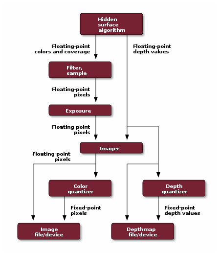
The output process is different for color, alpha, and depth information. (See the Imaging Pipeline diagram). The hidden-surface algorithm will produce a representation of the light incident on the image plane. This color image is either continuous or sampled at a rate that may be higher than the resolution of the final image. The minimum sampling rate can be controlled directly, or can be indicated by the estimated variance of the pixel values. These color values are filtered with a user-selectable filter and filterwidth, and sampled at the pixel centers. The resulting color values are then multiplied by the gain and passed through an inverse gamma function to simulate the exposure process. The resulting colors are then passed to a quantizer which scales the values and optionally dithers them before converting them to a fixed-point integer. It is also possible to interpose a programmable imager (written in the シェーディング Language) between the exposure process and quantizer. This imager can be used to perform special effects processing, to compensate for non-linearities in the display media, and to convert to device dependent color spaces (such as CMYK or pseudocolor).
Final output alpha is computed by multiplying the coverage of the pixel (i.e., the sub-pixel area actually covered by a geometric primitive) by the average of the color opacity components. If an alpha image is being output, the color values will be multiplied by this alpha before being passed to the quantizer. カラー and alpha use the same quantizer.
Output depth values are the screen-space z values, which lie in the range 0 to 1. Generally, these correspond to camera-space values between the near and far clipping planes. Depth values bypass all the above steps except for the imager and quantization. The depth quantizer has an independent set of parameters from those of the color quantizer.
RiDisplay ( RtToken name, RtToken type, RtToken mode, ...parameterlist... )
Choose a display by name and set the type of output being generated. name is either the name of a picture file or the name of the framebuffer, depending on type. The type of display is the display format, output device, or output driver. All implementations must support the type names "framebuffer" and "file", which indicate that the renderer should select the default framebuffer or default file format, respectively. Implementations may support any number of particular formats or devices (for example, "tiff" might indicate that a TIFF file should be written), and may allow the supported formats to be user-extensible in an implementation-specific manner.
The mode indicates what data are to be output in this display stream. All renderers must support any combination (string concatenation) of "rgb" for color (usually red, green and blue intensities unless there are more or less than 3 color samples; see the next section, Additional options), "a" for alpha, and "z" for depth values, in that order. Renderers may additionally produce "images" consisting of arbitrary data, by using a mode that is the name of a known geometric quantity, the name of a shader output variable, or a comma separated list of display channels (all of which must be previously defined with RiDisplayChannel).
Shader output variables may optionally be prefaced with a color and the shader type ("volume", "atmosphere", "displacement", "surface", or "light"); if prefaced with "light", the prefix may also include a light handle name. These prefixes serve to disambiguate the source of the variable data. For example, "surface:foo", "light:bar", or "light(myhandle):Cl" will cause the variables to be searched in the surface shader, first light shader to match, or light with handle "myhandle", respectively.
Note also that multiple displays can be specified, by prepending the + character to the name. For example:
RiDisplay ("out.tif," "file," "rgba", RI NULL);
RiDisplay ("+normal.tif," "file," "N", RI NULL);
will produce a four-channel image consisting of the filtered color and alpha in out.tif, and also a second three-channel image file normal.tif consisting of the surface normal of the nearest surface behind each pixel. (This would, of course, only be useful if RiQuantize were instructed to output floating point data or otherwise scale the data.) Renderers that support RiDisplayChannel should expect displays of the form:
RiDisplay ("+bake.tif," "file," "_occlusion,_irradiance", RI NULL);
Assuming _occlusion and _irradiance were both previously declared as floats using RiDisplayChannel, this RiDisplay line will produce a two-channel image.
Display options or device-dependent display modes or functions may be set using the parameterlist. Users can provide any set of parameters they want (provided they are supported by their display driver). Note that, in addition to any parameters provided by the user, the renderer will also provide a standard set of parameters that the user does not need to (and should not) provide.
RIB BINDING
Display name type mode ...parameterlist...
EXAMPLE
RtInt origin[2] = { 10, 10 };
RiDisplay ("pixar0," "framebuffer," "rgba," "origin," (RtPointer)origin, RI_NULL);
SEE ALSO
RiDisplayChannel ( RtToken channel, ...parameterlist... )
Defines a new display channel for the purposes of output by a single display stream. Channels defined by this call can then be subsequently passed as part of the mode parameter to RiDisplay.
Channels are uniquely specified for each frame using the channel parameter. Its value should be the unique channel name, along with an inline declaration of its type; for example, varying color arbcolor. Future references to the channel (i.e. in RiDisplay) require only the name and not the type (arbcolor). Channels may be further qualified by renderer specific options which may control how the data is to be filtered, quantized, or filled by the display or renderer; see RiDisplay for information on these options. Any such per-channel options should appear in the parameter list. If they are not present, then the equivalent option specified in RiDisplay will be applied.
DisplayChannel "varying point P" "string filter" "box"
   "float[2] filterwidth" [1 1] "point fill" [1 0 0]
DisplayChannel "varying normal N"
DisplayChannel "varying float s" "string filter" "gaussian"
   "float[2] filterwidth" [5 5] "float fill" [1]
DisplayChannel "varying color arbcolor"
Display "+output.tif" "tiff" "P,N,s,arbcolor"
   "string filter" "catmull-rom" "float[2] filterwidth" [2 2]
In this example, four channels P, N, s, and arbcolor are defined. P and s have channel options which control the pixel filter and default fill value. These four channels are then passed to RiDisplay via the mode parameter as a comma separated list. Because the DisplayChannel lines for N and arbcolor did not specify pixel filters, the filter specified on the Display line ("catmull-rom") will be applied to those two channels.
By default, the data for the display channel will come via the channel parameter, which will be interpreted by the renderer as a known geometric quantity, or the name of a shader output variable.
| Name | Type | Description |
|---|---|---|
| "dither" | float | This single value controls the amplitude of the dither added to the values of the output display. |
| "exposure" | float[2] | The two values required are gain and gamma. These control the exposure function applied to the pixel values of the output display in the same manner as RiExposure. |
| "fill" | float or color | The fill value is used in conjunction with the special pixel filters min, max, average, zmin, or zmax. The single value required represents the "fill" value used for any pixel subsamples that miss geometry. |
| "filter" | string | The name of the pixel filter to be used for the output display. The names of the standard pixel filters that may be passed to RiPixelFilter may also be used here (see the Pixel Filters section below for PRMan extensions). In addition, five special filters may be used: min, max, average, zmin, and zmax. The first three filters have the same meaning as the depthfilter argument to Hider, i.e. instead of running a convolution filter across all samples, only a single value (the minimum, maximum, or average of all pixel samples) is returned and written into the final pixel value. The zmin and zmax filters operate like the min and max filters, except that the depth value of the pixel sample is used for comparison, and not the value implied by the mode itself. These filters are useful for arbitrary output variables where standard alpha compositing does not make sense, or where linear interpolation of values between disjoint pieces of geometry is nonsensical. Note that when these filters are used, opacity thresholding is also used on that output to determine which closest surface to sample. |
| "filterwidth" | float[2] | The size in X and Y of the pixel filter to be used. Set to [0 0] to automatically use the standard size for the chosen pixel filter. |
| "interpretation" | string | Specifies alternate meanings for the display channel. The default interpretation is "standard", which means that the value for the channel is either a known geometric quantity or a shader output variable. An alternate interpretation is "alpha". When used in conjunction with "string opacity", this means that the value for the channel will be a float quantity synthesized from the specified opacity channel (similar to how the built-in display channel "a" is synthesized from "Oi"). |
| "matte" | int | When set to 0, this allows an AOV to entirely ignore Matte, thus forcing the AOV to show up for that object in the final image. (By default, "matte" [1] is in effect - the AOV responds to Matte.) |
| "opacity" | string | Specifies the name of a display channel whose value will be used to perform alpha compositing, or other transparency operations. (By default, the renderer will use Oi for these operations.) It will then be assumed that the shader performs premultiplication of the specified channels and that the channels are are shader output variables. The renderer will perform all subsequent compositing operations based on this assumption. |
| "quantize" | int[4] | These four values (zeroval, oneval, minval, and maxval) control how the output display is quantized. |
| "remap" | float[3] | This parameter causes pixel values stored in visible points to undergo a non-linear range compression. After pixel values are computed the compression is undone. The effect is that samples with large Ci values are confined to a more modest range before being averaged by the pixel filter. Without this mapping, any very small ultra-bright regions will splatter their brightness around to pixel filter-sized areas that may alias when clamped to the monitor's range. With the mapping, areas that have very few ultra-bright samples will come out a color that more nearly matches the average of the non-outliers, but large ultra-bright areas will, when the mapping is undone, still produce an ultra-bright result, as desired. The values a, b and c are parameters of the mapping:
|
| "source" | string | Specifies the known geometric quantity or shader output variable the renderer will use as a source of data in preference to the channel name (overriding the channel parameter). This allows the renderer to create multiple channels, each with unique names, that are copies of the same source data. |
| "statistics" | string | RIS-only. Indicates that this display channel should compute statistical measures on another display channel (specified via the source parameter). The statistics channel must have matching filter settings. The options available are: variance to estimate the variance of the samples in each pixel, mse which is the estimate of the variance divided by the actual number of samples per pixel, even for an image created from half the total camera samples, and odd for an image from the other half of the camera samples. |
Note
The renderer supports selecting array elements from DisplayChannels that are arrays. For example:
DisplayChannel "varying color[20] AOVOut1"
Display "+output.exr" "openexr" "P,N,AOVOut1:5"
RiPixelVariance ( RtFloat variation )
The color of a pixel computed by the rendering program is an estimate of the true pixel value: the convolution of the continuous image with the filter specified by RiPixelFilter. This routine sets the upper bound on the acceptable estimated variance of the pixel values relative to the true pixel values. It currently defaults to 0.001.
RIB BINDING
PixelVariance variation
EXAMPLE
RiPixelVariance (.01);
SEE ALSO
Imaging Pipeline
RiPixelSamples ( RtFloat xsamples, RtFloat ysamples )
Set the effective hider sampling rate in the horizontal and vertical directions. The effective number of samples per pixel is xsamples * ysamples. If an analytic hidden surface calculation is being done, the effective sampling rate is RI_INFINITY. サンプリング rates less than 1 are clamped to 1.
Note that this does not apply in PRMan's RIS mode.
RIB BINDING
PixelSamples xsamples ysamples
EXAMPLE
PixelSamples 2 2
SEE ALSO
RiVolumePixelSamples ( **RtFloat xsamples, RtFloat ysamples )
The VolumePixelSamples RI call allows a heterogeneous pixel sampling rate to be used for volumes only. By default, the number of samples taken is identical to that specified for PixelSamples. Prior to the pixel filtering stage, the pixel samples taken at heterogeneous rates are blended at subpixel resolution to ensure the final rendered pixel is as accurate as possible. This heterogeneous sampling can only be used with the stochastic hider.
Note that this does not apply in PRMan's RIS mode.
RIB BINDING
VolumePixelSamples xsamples ysamples
EXAMPLE
VolumePixelSamples 2 2
SEE ALSO
RiPixelFilter ( RtFloatFunc filterfunc, RtFloat xwidth, RtFloat ywidth )
Anti-aliasing is performed by filtering the geometry (or super-sampling) and then sampling at pixel locations. The filterfunc controls the type of filter, while xwidth and ywidth specify the width of the filter in pixels. A value of 1 indicates that the support of the filter is one pixel. A value of 0 requests the standard width for the chosen filter function. RenderMan supports nonrecursive, linear shift-invariant filters. The type of the filter is set by passing a reference to a function that returns a filter kernel value, e.g.:
filterkernelvalue = (*filterfunc)( x, y, xwidth, ywidth );
(where (x,y) is the point at which the filter should be evaluated). The rendering program only requests values in the ranges -xwidth/2 to xwidth/2 and -ywidth/2 to ywidth/2. The values returned need not be normalized.
The following standard filter functions are available:
RtFloat RiBoxFilter (RtFloat, RtFloat, RtFloat, RtFloat);
RtFloat RiTriangleFilter (RtFloat, RtFloat, RtFloat, RtFloat);
RtFloat RiCatmullRomFilter (RtFloat, RtFloat, RtFloat, RtFloat);
RtFloat RiGaussianFilter (RtFloat, RtFloat, RtFloat, RtFloat);
RtFloat RiSincFilter (RtFloat, RtFloat, RtFloat, RtFloat);
Additional built-in filters are also available.
A high-resolution picture is often computed in sections or panels. Each panel is a subrectangle of the final image. It is important that separately computed panels join together without a visible discontinuity or seam. If the filter width is greater than 1 pixel, the rendering program must compute samples outside the visible window to properly filter before sampling.
RIB BINDING
PixelFilter type xwidth ywidth
The type is one of: "box," "triangle," "catmull-rom" (cubic), "sinc" and "gaussian." The additional filters are "mitchell", "separable-catmull-rom", "blackman-harris", "lanczos", and "bessel" and "disk".
EXAMPLE
RiPixelFilter ( RiGaussianFilter,  2.0, 1.0);

PixelFilter "gaussian" 2 1
SEE ALSO
Definitions for the required RenderMan Interface filters are below. Keep in mind that the filter implementations may assume that they will never be passed (x,y) values that are outside the ([-xwidth/2, xwidth/2], [-ywidth/2,ywidth/2]) range.
Box Filter
RtFloat
RiBoxFilter (RtFloat x, RtFloat y, RtFloat xwidth, RtFloat ywidth)
{
    return 1.0;
}
Triangle Filter
RtFloat
RiTriangleFilter (RtFloat x, RtFloat y, RtFloat xwidth, RtFloat ywidth)
{
    return ( (1.0 - fabs(x)) / (xwidth*0.5) ) *
           ( (1.0 - fabs(y)) / (ywidth*0.5) );
}
Catmull-Rom Filter
RtFloat
RiCatmullRomFilter (RtFloat x, RtFloat y, RtFloat xwidth, RtFloat ywidth)
{
    RtFloat r2 = (x*x + y*y);
    RtFloat r = sqrt(r2);
    return (r >= 2.0) ? 0.0 :
         (r < 1.0) ? (3.0*r*r2 - 5.0*r2 + 2.0) :
         (-r*r2 + 5.0*r2 - 8.0*r + 4.0);
}
Gaussian Filter
RtFloat
RiGaussianFilter (RtFloat x, RtFloat y, RtFloat xwidth, RtFloat ywidth)
{
    x *= 2.0 / xwidth;
    y *= 2.0 / ywidth;
    return exp(-2.0 * (x*x + y*y));
}
Sinc Filter
RtFloat
RiSincFilter (RtFloat x, RtFloat y, RtFloat xwidth, RtFloat ywidth)
{
    RtFloat s, t;
    if (x >-0.001 && x < 0.001)
        s = 1.0;
    else
        s = sin(x)/x;
    if (y > -0.001 && y < 0.001)
        t = 1.0;
    else
        t = sin(y)/y;
    return s*t;
}
RiExposure ( RtFloat gain, RtFloat gamma )
This function controls the sensitivity and non-linearity of the exposure process. Each component of color is passed through the following function:
RIB BINDING
Exposure gain gamma
EXAMPLE
Exposure 1.5 2.3
SEE ALSO
RiQuantize ( RtToken type, RtInt one, RtInt min, RtInt max, RtFloat ditheramplitude )
Set the quantization parameters for colors or depth. If type is rgba, then color and opacity quantization are set. If type is z, then depth quantization is set. The value one defines the mapping from floating-point values to fixed point values. If one is 0, then quantization is not done and values are output as floating point numbers.
Dithering is performed by adding a random number to the floating-point values before they are rounded to the nearest integer. The added value is scaled to lie between plus and minus the dither amplitude. If ditheramplitude is 0, dithering is turned off.
Quantized values are computed using the following formula:
value = round ( one * value + ditheramplitude * random () );
value = clamp ( value, min, max );
where random returns a random number between +/- 1.0, and clamp clips its first argument so that it lies between min and max.
By default color pixel values are dithered with an amplitude of .5 and quantization is performed for an 8-bit display with a one of 255. Quantization and dithering are not performed for depth values (by default).
RIB BINDING
Quantize type one min max ditheramplitude
EXAMPLE
RiQuantize (RI_RGBA, 2048, -1024, 3071, 1.0);
SEE ALSO
レンダリング programs compute color values in some spectral color space. This implies that multiplying two colors corresponds to interpreting one of the colors as a light and the other as a filter and passing light through the filter. Adding two colors corresponds to adding two lights. The default color space is NTSC-standard RGB; this color space has three samples. カラー values of 0 are interpreted as black (or transparent) and values of 1 are interpreted as white (or opaque), although values outside this range are allowed.
RiカラーSamples ( RtInt n, RtFloat nRGB[], RtFloat RGBn[] )
This function controls the number of color components or samples to be used in specifying colors. By default, n is 3, which is appropriate for RGB color values. Setting n to 1 forces the rendering program to use only a single color component. The array nRGB is an n by 3 transformation matrix that is used to convert n component colors to 3 component NTSC-standard RGB colors. This is needed if the rendering program cannot handle multiple components. The array RGBn is a 3 by n transformation matrix that is used to convert 3 component NTSC-standard RGB colors to n component colors. This is mainly used for transforming constant colors specified as color triples in the シェーディング Language to the representation being used by the RenderMan Interface.
Calling this procedure effectively redefines the type Rtカラー to be:
typedef RtFloat Rtカラー[n];
After a call to RiカラーSamples, all subsequent color arguments are assumed to be this size.
If the Spectral カラー capability is not supported by a particular implementation, that implementation will still accept multiple component colors, but will immediately convert them to RGB color space and do all internal calculations with 3 component colors.
RIB BINDING
カラーSamples nRGB RGBn
The number of color components, n, is derived from the lengths of the nRGB and RGBn arrays, as described above.
EXAMPLE
カラーSamples [.3.3 .4] [1 1 1]

RtFloat frommonochr[] = {.3, .3, .4};
RtFloat tomonochr[] = {1., 1., 1.};
RiカラーSamples (1, frommonochr, tomonochr);
SEE ALSO
RiRelativeDetail ( RtFloat relativedetail )
The relative level of detail scales the results of all level of detail calculations. The level of detail is used to select between different representations of an object. If relativedetail is greater than 1, the effective level of detail is increased, and a more detailed representation of all objects will be drawn. If relativedetail is less than 1, the effective level of detail is decreased, and a less detailed representation of all objects will be drawn.
Note
The method of specifying and using level of detail is discussed in the Attributes section on Detail.
RIB BINDING
RelativeDetail relativedetail
EXAMPLE
RelativeDetail 0.6
SEE ALSO
Imager Shaders
As of PRMan 15, arbitrary imager shaders are supported, in addition to the two built-in imager shaders that have been available through the RiImager call. For more on arbitrary imager shaders, please consult the Imager Shaders application note; the built-in imager shaders are described below.
- clamptoalpha
takes no parameters, and merely assures that all color values are less than the value of the alpha channel prior to output. This is true even if the display mode of the image being generated is not an rgba image. Shaders that produce color values greater than one, as well as the pixel dithering process, can occasionally produce color values greater than the alpha value, potentially resulting in errors when the image is later composited over another image by programs that do not anticipate this possibility.
RiImager("clamptoalpha", RI_NULL);- background
takes a single parameter, background, of type uniform color. The rendered image is merged over the specified background color and all the alpha values are set to one.
Rtカラー bg = {0.4, 0.4, 1.0};
RiImager("background", "background", (RtPointer)bg, RI_NULL);
RiImager ( RtToken name, parameterlist )
Select an imager function programmed in the シェーディング Language. name is the name of an imager shader. If name is RI_NULL, no imager shader is used.
RIB BINDING
Imager name ...parameterlist...
EXAMPLE
RiImager ("cmyk," RI_NULL);
SEE ALSO
RiPixelSampleImager ( RtToken name, parameterlist )
Select a pixel sample imager function programmed in the シェーディング Language. name is the name of an imager shader. If name is RI_NULL, no imager shader is used.
RIB BINDING
PixelSampleImager name ...parameterlist...
EXAMPLE
RiPixelSampleImager ("combineAovs," RI_NULL);
SEE ALSO
Frame Buffer Control
There are several options which can be enabled through the parameter list of the RiDisplay call. These options, naturally enough, influence the use of the display device.
- Display Origin
The origin of the output window on a frame buffer device can be set using the display origin option. For example, to place the origin of the output window at the point (512,384):
RtInt o[2] = {512, 384}; RiDisplay("name", "framebuffer", "rgba", "origin", (RtPointer)o, RI_NULL);- Display Merge
Frame buffers can be configured to merge the generated image over an existing image with the display merge option:
RtInt flag = 1;
RiDisplay("name", "framebuffer", "rgba",
          "merge", (RtPointer)&flag, RI_NULL);
The merge option works only if the selected display driver supports it.
- Device Resolution
Some file formats (e.g., TIFF, Postscript) support the concept of device resolution, meaning how many pixels appear per physical unit of measure (e.g., dots per inch). Two display options provide a way to document these values into files generated by PRMan. A string specifying the physical unit of resolution can be set with the resolutionunit option. A pair of integers specifying the number of pixels per resolution unit in width and height can be set with the resolution option. For example, to set the resolution at 72 dpi:
RtString ru[1] = "inch";
RtInt r[2] = {72, 72};
RiDisplay("name", "TIFF", "rgba",
          "resolution", (RtPointer)r,
          "resolutionunit", (RtPointer)ru, RI_NULL);
Currently, the TIFF file driver considers both resolutionunit, which must be "inch" or "centimeter", and both resolution values. The PICT and Postscript drivers only consider the first resolution value, as images in these formats must have the same value in both directions, and implicitly assume inches as the resolution unit.
- Output Compression
The TIFF driver also accepts an option to set the compression type, which may be "lzw", "packbits", "zip" (the default), "pixarlog", or "none":
RtString cmp[1] = "none"; RiDisplay("name", "TIFF", "rgba", "compression", (RtPointer)cmp, RI_NULL );- Custom Display Driver Options
- Custom display drivers may also accept other display options, but they must be declared with RiDeclare before RiDisplay can accept them and pass them through to the custom driver.
- Filename Formatting
Special formatting can be done on the filename parameter to RiDisplay. The "#" character is recognized as a special lead-in character in file names. The action taken depends on the character after the "#".
Optional Formatting Prefixes Prefix Description #f Is replaced with the frame number as specified to RiFrameBegin. By default it is inserted into the filename as three digits with leading zeroes. The number of digits can be controlled using #*width*f, where *width* is a string of decimal digits. #s Replaced with the frame sequence number. This number is incremented for every frame block regardless of the frame number. Takes an optional width as with #f. #n Replaced with a running sequence number. This number is incremented every time the renderer outputs an image file, regardless of the frame number. Takes an optional width as with #f. #d Replaced with the requested display type. #p Is replaced with the processor number in a multiprocessor rendering. This should never be used in a file name during automatic multiprocessor rendering such as through netrender. #P Is replaced with the total processor count in a multiprocessor rendering. This should never be used in a file name during automatic multiprocessor rendering such as through netrender. ## Is replaced with a single #.
Example:
RiFrameBegin(15);
RiDisplay("test#f.#d", "tiff", ...);

      Produces the file name: ``"test015.tiff"``.
- Arbitrary Output Variables
PRMan supports the use of multiple simultaneous output displays for a single render. As described in the RiDisplay section, this allows rendering of a display mode that can be the name of a known geometric quantity, a comma separated list of channels all of which were specified with RiDisplayChannel, or the name of a shader output variable. Multiple display specifications may be specified by prepending the + character to the display name.
When using multiple output displays, PRMan will recognize the RiDisplay options enumerated above, as well as the following special parameters when they occur in the RiDisplay parameter list:
Option Description int[4] quantize These four values (zeroval, oneval, minval, and maxval) control how the output display is quantized. float dither This single value controls the amplitude of the dither added to the values of the output display. float[2] exposure The two values required are gain and gamma. These control the exposure function applied to the pixel values of the output display in the same manner as RiExposure. string filter The name of the pixel filter to be used for the output display. The names of the standard pixel filters that may be passed to RiPixelFilter may be used here (see the Pixel Filters section below for PRMan extensions).
In addition, five special filters may be used: min, max, average, zmin, and zmax. The first three filters have the same meaning as the depthfilter argument to Hider, i.e. instead of running a convolution filter across all samples, only a single value (the minimum, maximum, or average of all pixel samples) is returned and written into the final pixel value. The zmin and zmax filters operate like the min and max filters, except that the depth value of the pixel sample is used for comparison, and not the value implied by the mode itself. These filters are useful for arbitrary output variables where standard alpha compositing does not make sense, or where linear interpolation of values between disjoint pieces of geometry is nonsensical. Note that when these filters are used, opacity thresholding is also used on that output to determine which closest surface to sample.
float[2] filterwidth The size in X and Y of the pixel filter to be used. Set to [0 0] to automatically use the standard size for the chosen pixel filter. PRMan 11 introduced the special variable __CPUtime, which may also be used as a mode for an arbitrary display:
Display "+costfilename.tif" "tiff" "__CPUtime"
This mode will result in an image that profiles how long it takes to shade each micropolygon as it renders. The data stored will be the amount of time it took to shade each micropolygon in seconds.
Pixel Filters
In addition to the standard pixel filter functions in the Specification, PRMan supports these additional pixel filters:
RiMitchellFilter
RIB form: "mitchell"
The recommended filter from Don Mitchell and Arun Netravali's 1988 Siggraph paper on reconstruction filters - the separable version of the (1/3, 1/3) filter.
RiSeparableCatmullRomFilter
RIB form: "separable-catmull-rom"
A separable version of the Catmull-Rom filter.
RiBlackmanHarrisFilter
RIB form: "blackman-harris"
A separable 4 term (-92 dB) Blackman-Harris filter.
RiLanczosFilter
RIB form: "lanczos"
A Lanczos-windowed sinc filter. Use with width 4x4 for the 2-lobe variant and 6x6 for the 3-lobe variant.
RiBesselFilter
RIB form: "bessel"
A a radially symmetrical bessel function which is the inverse Fourier transform of the cylindrical box, that is, the the perfect lowpass filter whose cutoff is circular in the frequency domain.
RiDiskFilter
RIB form: "disk"
Like the box filter, but circular (i.e., a radial box filter).
レンダリング Options
レンダリング programs may have additional implementation-specific options that control parameters that affect either their performance or operation. These are all set by the following procedure. In addition, a user can specify rendering option by pre-pending the string "user:" onto the option name. While these options are not expected to have any meaning to a renderer, user options should not be ignored. Rather, they must be tracked according to standard option scoping rules and made available to shaders via the option function.
レンダリング
Option "render" "int rerenderbake" [1]
Option "render" "string rerenderbakedbdir" "dirname"
Option "render" "string rerenderbakedbname" "worldname"
Checkpointing
New in RPS 19 - PRMan 19 introduces new options for periodically writing checkpoints when the incremental path tracing mode is enabled (in RIS or REYES).
Option "checkpoint" "uniform int interval" [i]
                    "uniform int exitat" [i]
                    "uniform int keepfiles" [b]
For the interval and exitat values, positive values will specify seconds, negative values will specify increments, and zero - [0] - will disable it. For convenience, strings will also be accepted, e.g.: "string exitat" "8.0h" where the suffix may be (i)ncrements, (s)econds, (m)inutes, (h)ours, or (d)ays. They are "off" by default. Users should also consult the prman manual for more information about the -checkpoint and -recover arguments.
Note: checkpointing requires a display driver that supports multi-channel images and floating point output. Of the built-in drivers, only the standard TIFF and OpenEXR driver are capable of this, and only OpenEXR can resume a checkpointed render. Note that the checkpoint option can generate significant amounts of I/O, especially if the interval is small.
For more information, see the チェックポイント & リカバリー page of the RIS ユーザーガイド.
Re-rendering
Option "rerender" "int[2] lodrange" [finest coarsest]
Specifies the range of levels of detail to use in the progressive refinement of the image when re-rendering. The finest level of detail is always 0, so specifying [0 0] will re-render only the most detailed image. The number of levels available depends on the re-rendering algorithm. The defaults are [0 N], where N is scene-dependent. [Note: it is possible to set the level of detail > 0, but it can lead to pixelization.]
With the raytrace re-renderer, this option only has effect when the "int progressive" optional parameter to EditWorldBegin is true (set to 1) or the Hider options are set to "string integrationmode" "path" and "int incremental" 1. The option may be changed within the EditWorld block. N is capped to 3 when using the raytrace re-renderer: LOD 0 renders final quality pixels, LOD 1 renders single-sampled, normal size pixels, LOD 2 renders 4x-sized pixels, and LOD 3 renders 16x-ized pixels. When using adaptive sampling distribution ray tracing, LOD 0 also causes the rerender to make multiple passes over each bucket, adding a new sample to every pixel each time.
Bucket Size
PRMan subdivides the screen into blocks of pixels termed buckets when resolving the visible surface calculations. Large buckets are more efficient and permit larger grids to be used (see below). Large buckets however require more memory. The bucketsize option is used to specify the n-by-m size of a bucket, in pixels; for example:
RtInt bs[2] = {12, 12};
RiOption("limits", "bucketsize", (RtPointer)bs, RI_NULL);
Grid Size
The gridsize option determines the maximum number of micropolygons that can be shaded at one time. This is another option that can be used to control the tradeoff between computational efficiency and memory utilization. The number of active micropolygons directly affects the amount of memory required to render an image since the state of each active micropolygon must be maintained until it is resolved. Large grids in general are more efficient to shade since the shading machinery is invoked once for a large number of micropolygons, rather than many times for a fewer number of micropolygons. However, larger grids require larger temporary variable buffers for shading (particularly when textures are involved in the shading process) and produce large increases in the number of active micropolygons. A minimal value for this parameter can be calculated by dividing the bucket size by the micropolygon size set with the RiシェーディングRate request; e.g., a shading rate of 4.0 and a bucket size of 12 * 12 gives a gridsize of 12 * 12/4 = 36. This is minimal in the sense that values smaller than this don't save much memory. The following sets the maximum grid size to 36:
RtInt gs = 36;
RiOption("limits", "gridsize", (RtPointer)&gs, RI_NULL);
Hair Length
Option "dice" "maxhairlength" [-1]
PRMan 16.3 introduced a new optional parameter to control hair length. It defaults to -1, which uses min(bucketsizex, bucketSizeY). If set to a non-negative value this option overrides the default. Normally, hairs are split into roughly bucket-sized chunks. This option can be used to set a length smaller than the bucket size, which improves the accuracy of their bounds and therefore ray tracing performance and memory-lifetime management. As a temporary solution to improve the performance of ray-traced hair, maxhairlength may be set very small (4, for example), which allows the hair to be split finer without the need to set a small global bucket size. Note that this option will improve the performance of ray-traced curves, but may have a negative impact on REYES-only renders.
Starting with version 17.0b1, we've made more fundamental changes to spatially group the curve geometry into tighter bounding volumes (while also forming larger shading grids to improve shading performance and avoid a negative impact on REYES rendering performance), and thus the "dice:maxhairlength" option, while perhaps not yet quite deprecated, appears in our testing to have much less of an effect on ray tracing performance (since the new algorithm is already tightly limiting the length/volume of the hairs when forming the improved bounding volume hierarchy). Our current recommendation is probably best expressed as: with the new implementation, we'd expect that there may not be much of a performance benefit to explicitly setting the "dice:maxhairlength" option (the default settings should work well out-of-the-box). However, we haven't removed the "dice:maxhairlength" option, so it is still possible to control this, if you like (and we would be interested in any feedback you have).
This option may be deprecated at some point in the future.
Hair Width
Option "hair" "float minwidth" [0]
The option specifies the minimum width in pixels for rendered RiCurves primitives; hair below this minimum width will be automatically widened by the renderer. Use of this option can help avoid aliasing when rendering hair into shadow maps. It is off (0) by default. See the RiCurves Primitive application note for more details and recommendations.
As of PRMan 19, "minwidth" is also respected for ray tracing. All ray types, including transmission, use a stochastic test to determine whether a widened curve has been hit. T
Curve Orientation
Option "curve" "int orienttotransform" [-1]
Curve Cacheing
Option "curve" "int usegutcache" [0|1]
Stochastic Transparency
Option "curve" "int stochasticshadows" [0|1]
Arbitrary Bucket Order
PRMan, as of version 13.5, allows the user to specify that the image be rendered in other orders than the default left to right, top to bottom order. This option can be used to decrease memory footprint for scenes that have a wide aspect ratio by choosing the vertical order. The option is specified via:
Option "bucket" "string order" [ "horizontal" ]
The bucket orders that are currently supported are:
horizontal: left to right, rendering scanlines from top to bottom(default)
vertical: top to bottom, rendering vertical scanlines from left to right
zigzag-x: the same as horizontal, except direction reverses at end of scanlines
zigzag-y: the same as vertical, except direction reverses at end of scanlines
spacefill: renders the buckets along a hilbert spacefilling curve
spiral: renders in a spiral from the center of the image; "spiral" can take the optional parameter "orderorigin" to indicate where the spiral should begin, e.g.
Option "bucket" "string order" [ "spiral" ] "orderorigin" [256 256]
The default remains the center of the image (xRes/2, yRes/2).
random: renders buckets in a random order (inefficient memory footprint)
If any of the display drivers in use require scanline order, then all display drivers will buffer all of the image data in memory if an order other than horizontal or zigzag-x is used.
Threads
There is an advanced Ri option that can be used to explicitly set the exact number of threads that the renderer uses for a RIB file.
Option "limits" "int threads" [0]
You can override the rib option with the following command line flag:
prman -t:N render.rib
where N is one of the supported settings below. The default setting is 0.
Supported settings:
- 1: just use 1 thread for computation. The renderer will not check to see how many cores/hyper-threads your machine has, it will just use 1.
- 2 - 128: use the specified number of threads for computation. The renderer will over-schedule if you specify a number higher than the number of threads on your machine.
- 0: query your machine to determine how many threads are on the machine and only use that many to avoid over-scheduling your machine.
- -1: query your machine and use all the threads on the machine except for one. This parameter is useful for interactive renders to leave a thread for the bridge product to use.
- -N: use all the threads on the machine minus N (where n is an integer)
Ray Tracing
Option "trace" "int maxdepth" [25]
Option "trace" "float specularthreshold" [10]
This option is obsolete, as of PRMan 16.0.
An angular threshold that was used to distinguish between specular and diffuse ray sampling patterns. This threshold was used by gather(), indirectdiffuse(), and occlusion() to automatically set the ray type. The type was set to "diffuse" if the coneangle was larger than "specularthreshold", and otherwise set to "specular". This option is now obsolete, since the ray type can be set explicitly in the individual shadeops instead.
Option "trace" "int decimationrate" [1]
Pretessellation
Option "dice" "int pretessellate" [1]
Off-Screen Strategy
Option "dice" "float offscreenmultiplier" [f]
Photon
Option "photon" "int emit" [0]
Generates a photon map in a pre-pass while only parsing and constructing the scene once. After parsing the RIB file, PRMan will emit and trace the specified number of photons and then render the scene. Requesting the emission of 0 photons disables the pre-pass.
Note that for backward compatibility, the original photon hider syntax is still valid; it simply traces the photons and then skips the render.
Option "photon" "string lifetime" [file]
For additional information, consult the New Photon Mapping Features application note.
Shade
Option "shade" "int directlightingsamples" [64]
Option "shade" "int debug" [1]
Option "shade" "int derivsfollowdicing" [1]
Option "shade" "int checknans" [0]
Option "shade" "float defcache" [0]
Option "shade" "float objectcache" [1.5]
Option "shade" "int saveshaderstate" [0]
Option "shade" "int directlightinglocalizedsampling" [-1]
Enables a 'light localization' scheme to enable the renderer to determine the relative importance of lights for each point being shaded. This calculation carries a certain performance burden, but in nearly all cases produces much cleaner images given the same amount of render time. Here are the currently supported light localization settings:
- -1: Accept default (mode 1 for REYES, mode 3 for RIS).
- 0: disables localization. The relative importance of lights is fixed for all locations in the scene.
- 1: Light importance based on intensity, distance and angle with respect to receiving point in scene. Default for REYES, but this mode has proved too expensive for most RIS scenes we have tested.
- 2: unsupported
- 3: Similar to 1, but optimized for RIS rendering.
- 4: Similar to 1 and 3, but enhanced with a learning algorithm that adjusts relative importance as light is propagated through the scene.
When enabled (not '0'), localization will override - and ignore - any fixed sample count settings that are present on lights.
The influence of lights on a shade point is computed at shutter open time, and does not currently take into account the relative motion between light and shade point. Under very rare circumstances, you may experience artifacts where a light is incorrectly deemed invisible to the shade point for the duration of the shutter-open period. The only recourse in such circumstances currently is to disable localization by setting the option to '0'.
Visible Point (VP) Options
Option "limits" "float vprelativeshadingrate" [0]
Visible point shading is performed on the final sub-pixel samples, after all grid shading of geometry in a bucket is completed.
Every sub-pixel sample location on objects with visible point shaders bound to them has the shader run on it, which can be expensive when PixelSamples is high. The vprelativeshadingrate option causes the visible point shading on some number of neighboring subsamples to be estimated by executing the shader on a single representative subsample.
Although similar in spirit to the relativeshadingrate Attribute, vprelativeshadingrate is instead an Option applied to the entire frame. It is a multiplier applied to the accumulated local shading rate (attribute) associated with visible point shaded primitives, and provides a simple way to reduce the cost of visible point shading on frames having a high PixelSamples value.
A vprelativeshadingrate value of 1.0 means use the local accumulated シェーディングRate area as the visible point shading estimation region. A considerably larger vprelativeshadingrate, e.g. 20, will result in larger, potentially "blocky" visible point shading regions, but will run correspondingly faster. For example, a vprelativeshadingrate of 8.0, and an object with a local シェーディングRate of 0.5, gives (0.5 x 8.0) = 4.0, meaning that a single visible point shading result will be reused over a shading region of approximately 4 pixels.
vprelativeshadingrate defaults to zero, meaning that visible point shading is run on all subsamples. Set it to 0.5 or 1.0 to allow the local シェーディングRate to have its intuitive effect on visible point shading results.
Option "limits" "float vpdepthshadingrate" [0.01]
Option "limits" "uniform int vpinteriorheuristic" [0]
Option "limits" "uniform int vpvolumeintersections" [5]
Opacity Threshold
Only objects with opacities greater than or equal to the opacity threshold will appear in shadow maps and other z files. The threshold is a color value (as is the shader opacity value Oi). Therefore, if any channel of opacity is greater than or equal to the threshold, the object will appear in shadow maps (and other zfiles). The default value for the opacity threshold is {0.996, 0.996, 0.996} (255/256) or almost completely opaque. This means that partially or completely transparent objects are not rendered into shadow maps or zfiles; only objects which are (almost) completely opaque are rendered. If the opacity threshold is set to {0.0, 0.0, 0.0} all objects will be rendered into the shadow map. The opacity threshold can be controlled with the following option:
Rtカラー thres = {0.30, 0.30, 0.30};
RiOption("limits", "zthreshold", (RtPointer)thres, RI_NULL);
Opacity Culling
When rendering scenes with a large number of semi-transparent layered objects (e.g. hair), the opacity culling threshold can be set for a significant time and memory savings. Essentially, a stack of visible points whose accumulated opacity is greater (in each channel) than the specified limit will be considered fully opaque by the hider, and objects behind the stack will be culled. This opacity limit is controlled with the following option:
Rtカラー thres = {0.995, 0.995, 0.995};
RiOption("limits", "othreshold", (RtPointer)thres, RI_NULL);
The opacity threshold is {0.996, 0.996, 0.996} by default.
This threshold also sets the ray termination criteria for automatic continuation rays. Trace/gather rays apply a scheme similar to the one described above camera samples (visible points), they continue through semi-transparent objects accumulating color and opacity, until the opacity threshold is reached. The gather "othreshold" parameter can be used to override the global threshold for special cases such as non-illuminance ray probes.
Because the opacity threshold allows the renderer to stop processing on a stack of visible points before they are truly opaque, this can lead to apparent holes in alpha channels. To correct for this, an additional stochastic Hider option may be used:
Hider "hidden" "int othresholdclamp" [0]
The default value is 0, meaning the traditional othreshold behavior where pixels may have reduced opacity. If the value is 1, then when then othreshold is reached, the opacity of the pixel will be set to 1.
Shadow Maps
In some cases shadow maps may exhibit a problem with surface self-shadowing. This manifests itself as small gray spots all over objects in shadow, and is caused by numerical inaccuracy in computing the depth of a particular surface. If a depth computed when generating the depth map is slightly less than that computed when rendering the image, a shadowing light source shader will interpret this as a shadow and produce a gray spot. This can be solved by using the shadow option to add a small bias value to the values in the depth map when rendering the final image. Care must separate from the objects casting them. The bias parameter is set as follows:
RtFloat bias0 = 0.35;
RiOption("shadow", "bias", (RtPointer)&bias, RI_NULL);
Note that this bias value can be overridden by a parameterlist value supplied in the shadow call of the shader.
Previously, shadow maps always contained the minimum depth value calculated from all depth values within the current pixel. The user now has control over the function that computes the output depth value for each pixel. This is controlled by a new Hider option called "depthfilter". You can now select between the minimum, maximum, or average of the pixel depth values to output.
サンプル, used in conjunction with the "jitter" parameter:
Hider "hidden" "jitter" [0] "depthfilter" "min"
Hider "hidden" "jitter" [0] "depthfilter" "max"
Hider "hidden" "jitter" [0] "depthfilter" "average"
In addition, there is one special version of the depth filter that works a bit differently - midppoint. For each sample position, it calculates the depth as the midpoint between the object that is closest to the viewpoint and the second closest object. This requires a bit more time than the other techniques, but generates z values that may require less tweaking and biasing. This method was proposed by Andrew Woo of Alias Research in Graphics Gems III, page 338. This method is specified by the Hider statement:
Hider "hidden" "jitter" [0] "depthfilter" "midpoint"
Please note that the "depthfilter" option is only useful if your display includes the "z" channel, e.g. "rgbaz" or "rgbz".
PRMan 3.8 introduced an enhanced shadow shadeop supporting a new (at the time) method of generating soft shadows with true penumbral fadeout, simulating shadows of area light sources. The method uses multiple rendered shadow maps to infer visibility information from a light source whose extended geometry is also specified in the shadeop. For more details, see the Application Note on soft shadows.
テクスチャ フィルタリング
The default filter used by the texture shadeop can be set using the following RIB texture option:
Option "texture" "texturefilter" ["force:filtername"]
where filtername is one of: box, disk, gaussian, lagrangian, or radial-bspline. The keyword force: is optional. If set, the filter parameter of the texture shadeop is ignored and the filter specified by the option is used. Without the force:, only texture calls without a specified filter will get the default. The default filter is box.
Two texture options control the use of high quality texture filtering options. These allow the selection of higher quality filtering in the shading language to be enabled or disabled. When disabled, the "filter" and "lerp" optional parameters to texture() and environment() have no effect.
- enable gaussian
- Enables the use of a gaussian filter when filtering the texture sample data from a texture or environment map. Takes a floating point value. A value of 0.0 disables the selection of the gaussian filter. A value of 1.0 enables the selection of the gaussian filter.
- enable lerp
- Enables the interpolation of two texture resolution levels to insure smooth transitions between resolution levels. The data will be interpolated between the resolutions above and below the ideal resolution for the shading sample. Takes a floating point value. A value of 0.0 disables the selection of interpolation. A value of 1.0 enables the selection of interpolation.
They are enabled by default. Here is an example of disabling high quality filtering:
RtFloat off = 0.0;
RiOption("texture", "enable gaussian", (RtPointer)&off,
            "enable lerp", (RtPointer)&off,
            RI_NULL);
Deep テクスチャ Compression
PRMan supports three optional methods of error tolerance for lossy compression of deep texture files (including traditional deep shadow maps, area shadow maps, and deep compositing outputs).
Option "limits" "float deepshadowerror" [0.01]
Option "limits" "float deepshadowsimplifyerror" [-1]
and
Option "limits" "float deepshadowdeptherror" [1.0]
deepshadowerror is essentially as described in Lokovic and Veach's "Deep Shadow Maps". Setting it to a high value will result in lower numbers of samples stored in each pixel function; this can be verified by using the dsview or txinfo utilities.
PRMan 16 added a secondary lossy compression method, based on the Ramer-Douglas-Peucker line simplification algorithm. Error tolerance for this secondary method is controlled by the deepshadowsimplifyerror option. The -1 default for tells the renderer to use the deepshadowerror value for both compression methods (i.e. both are run with the same value) and 0 disables the option. As with deepshadowerror, higher values will result in lower numbers of samples stored. Note that this compression method is applied in addition to the original algorithm (unless set to 0).
PRMan 16.5 introduced scale-adaptive deep file compression, enabled via deepshadowdeptherror. This is a multiplier on the diagonal length of a projected texel facing the map camera. Setting it to zero (the default) disables the new filtering, and adjusting it up or down makes it more or less agressive, respectively.
For more information about compressing deep texture files, please consult the Deep Compositing application note.
Memory
Grid Memory
Like gridsize, the gridmemory option can be used to control the tradeoff between computational efficiency and memory utilization by setting a desired "high water mark" for grid memory. Exceeding this limit (specified in KB) will cause the renderer to attempt to discard grids that can be regenerated later by re-dicing the high-level gprim from which they originated. The default value, 0, means that grid memory is unlimited.
Option "limits" "int gridmemory" [0]
Procedural Memory Limit
PRMan 14.0 introduced the ability to unload the contents of expanded procedurals. (In the current release, this is restricted to ray-traced procedurals; procedurals visible to the camera cannot be unloaded ahead of their usual bucket lifetime.)
Option "limits" "int proceduralmemory" [0]
the amount of memory, specified in kilobytes, that the renderer should devote to the geometric contents of expanded procedurals (this includes memory tracked in the GPrim memory, Vertex vector memory, and Catmull-Clark/Loop subdivision memory categories). The default value is 0, which disables procedural unloading. A value of 1048576 represents one gigabyte of memory.
If the renderer detects that the amount of geometric memory used by expanded procedurals exceeds this limit, the renderer will begin unloading the contents, as well as any associated spatial acceleration data overhead, of the least recently used procedural primitive. Specifying a limit of 0 turns off unloading altogether: no procedural created geometry will be ever removed from the renderer. The renderer correctly handles the case of nested procedurals: child procedurals will be removed prior to their parent procedurals, to ensure that if procedural reload occurs, no duplicate geometry will be created.
The Procedural cache entries, Procedurals unloaded and Procedurals reloaded entries under the geometry category in the XML statistics allow you to monitor how often the renderer is unloading and reloading procedurals.
On an as-needed basis, the renderer may subsequently rerun an unloaded procedural in order to restore its contents to the scene. For DelayedReadArchive procedurals, this amounts simply to re-reading the RIB file. For RunProgram procedurals, the datablock will be resent to the program (the socket connection to the program will remain open until FrameEnd for this purpose). For procedural primitive DSOs, the renderer will resend the data string to your ConvertParameters() method, and then reissue calls to the Subdivide() and Free() methods. For all other procedurals (this includes any calls made from a DSO procedural directly to RiProcedural which do not pass in RiProcDynamicLoad as the subdivide method), the renderer will defer calls to the passed in free method until end of frame, and will assume that the subdivide method can be called repeatedly with the same data pointer that was used initially with the RiProcedural call.
Important
If your procedural cannot be used in this way because of side effects or performance reasons - for example, they allocate large amounts of memory that should not be freed, or their Free methods or program exit cannot be delayed - your procedural may not behave well when reloaded. If this is an issue, the unloading of the procedural can be disabled by setting the "procedural" "unloadable" attribute to a value of 0. Procedurals with this attribute value will not have their Free methods deferred.
The default proceduralmemory limit can also be set in the rendermn.ini, like so:
/prman/proceduralmemory 1048576
Ray Tracing Memory
The ray tracing system also provides options to manage the balance of speed versus memory.
Option "limits" "int geocachememory" [204800]
Option "limits" "int hemispheresamplememory" [10240]
Option "limits" "int opacitycachememory" [1024000]
Option "limits" "int radiositycachememory" [1024000]
Polygon Memory
PRMan 18 introduced a new reduced memory implementation for rendering detailed polygonal meshes. It is enabled by default, but can be disabled with the following option:
Option "polygon" "int reducedmemory" [0]
or via the rendermn.ini file by appending the following line:
/prman/polygon/reducedmemory 0
Additionally, the behavior of the renderer when input data contains non-planar polygons is different from previous versions of PRMan. In particular, with the default settings, the behavior when the input data contains non-planar polygons is undefined (whereas previous versions would support non-planar polygons by default). It is possible to re-enable support for non-planar polygons via an option:
Option "polygon" "int nonplanar" [1]
or via rendermn.ini by appending the following line:
/prman/polygon/nonplanar 1
Render Memory
There is a Linux-only option for limiting memory consumption.
Option "limits" "float rendermemory" [1.0]
テクスチャ Memory
The texture system caches data that is read from texture files. The user can modify the limits on the total amount of memory devoted to cached texture data. Large caches increase texture mapping efficiency (particularly on a lightly-loaded host), but obviously can bloat the total memory usage. The texture-cache memory size is specified in kilobytes with the following option:
RtInt tm = 8192;
RiOption("limits", "texturememory", (RtPointer)&tm, RI_NULL);
Or, in the RIB file:
Option "limits" "int texturememory" [2048]
The default value us 50MB.
With the introduction of Per-Face テクスチャs in PRMan 15 there is an additional option that limits the total amount of memory for "ptextures". The RIB syntax is:
Option "limits" "int ptexturememory" [2048]
Or in the rendermn.ini with:
/prman/ptexturememory 2048
The default value is 40MB.
Additionally, users can limit the number of cached PTex files, via:
Option "limits" "int ptexturemaxfiles" [128]
Or in the rendermn.ini:
/prman/ptexturemaxfiles 256
The default value is 128.
As of PRMan 15, deep shadow maps use a memory limit rather than a number of tiles as the largest size of the deep shadow cache it will try to maintain. The option deepshadowtiles is still used as the initial number of tiles the cache is optimized for. The options are expressed thusly:
Option "limits" "int deepshadowmemory" [102400]
and:
Option "limits" "int deepshadowtiles" [1000]
The deepshadowmemory is specified in K, as are all other memory limits. The deepshadowtiles limit is used as the initial number of tiles the cache is optimized for. The cache will grow from this number of tiles until the memory limit is reached, at which point it throws away tiles whenever the limit is crossed. Note that the default value has been increased from 100 to 1000.
RenderMan Pro Server 15 also introduced the ability to have PRMan use an almost constant amount of memory for caches, regardless of the number of threads. Prior to version 15, memory limits varied based on the number of threads being used. This default behavior is restored via the .ini in PRMan 16; users who wish to restore the 15-style limits need to change their /prman/constantmemorylimit setting in rendermn.ini to 0 to disable thread-independent memory limits. Note that using more threads does typically require more memory for the caches to achieve similar cache performance.
3D テクスチャ Memory
Points and octree nodes read by texture3d() are stored in caches. This makes it possible to efficiently read data from very large organized point cloud files.
The default size of the caches is 10 MB, but it can be controlled with Option "limits" "int pointmemory" and Option "limits" "octreememory". The size is specified in kB, so to specify two 50 MB caches, use:
Option "limits" "int pointmemory" [51200]
Option "limits" "int octreememory" [51200]
Alternatively, the cache sizes can be specified in the rendermn.ini file, thusly:
/prman/pointmemory          51200
/prman/octreememory         51200
As usual, the Option overrides the rendermn.ini setting if both are used.
However, the specified cache sizes are only used as a guideline. The number of cache entries is determined by the cache size and the number of data per point in the first point read. If any of the following points have more data, the point cache entries will be enlarged on-the-fly, and the end result is a cache using more memory than specified by the option (or rendermn.ini file). This also applies to the octree cache. Additionally, in multithreaded execution there are caches for each thread, so the total cache size increases as more threads are used.
Similarly, the 3D texture system caches bricks that are read from brick map files. The user can modify the limit on the amount of memory used for cached bricks. The brick cache memory size is specified in kilobytes with the following option:
Option "limits" "int brickmemory" [10240]
Statistics
Statistics output is controlled by the following RIB option:
Option "statistics" "int endofframe" [*level*]
The value of *level* should be either 0 (off) or 1 (on). (Values greater than one no longer increase the level of detail. Level-of-detail is controlled by post-processing the statistics XML file.)
Summary statistics are reported in plain text, while detailed statistics are reported as XML. Output filenames are specified by the following options:
Option "statistics" "string filename" [ "filename.txt" ]
Option "statistics" "string xmlfilename" [ "filename.xml" ]
Either filename may be the empty string, which disables that kind of output, or "stdout", in which case the output is displayed on the console. (Note that XML written to stdout might not be well formed if procedural or shader plugins also write to stdout.) The default values of "filename" is "stdout", and the default value of "xmlfilename" is the empty string. These defaults can be changed by editing the RenderMan configuration file (etc/rendermn.ini).
The "xmlfilename" can be set to a special value, "usefilename", which indicates that XML statistics should be written to the filename that would normally receive the plain-text statistics. Doing so can facilitate incorporating XML statistics into pipelines without requiring changes to RIB generators.
Important
The stylesheet behavior described below has been superceded as of PRMan 15.0. Due to security restrictions in modern browsers, having the XML style sheet as a separate file in a separate directory will no longer generate a correct stats display. Instead, we now embed the stylesheet directly into the stats file. While this increases the size of each stats file, the results are more useful in modern browsers. The default behavior can be changed via the rendermn.ini, restoring the old behavior, like so:
/prman/statistics/embedstylesheet false
The XML file is linked to a stylesheet for viewing in a Web browser. Sometimes the Web browser is unable to locate the stylesheet. This commonly occurs if the statistics are generated on a renderfarm but viewed on workstation that does not have the stylesheet in the same location.
The location of the XML stylesheet can be specified by the following option:
Option "statistics" "string stylesheet" [ "URL" ]
The URL can be relative (e.g. a filename). The default location of the stylesheet can also be specified in the etc/rendermn.ini configuration file. See the XML Frame Statistics application note for more information.
Shader profiling is enabled with the following option, which specifies the location of the output file. See the Shader Profiling application note for more information.
Option "statistics" "string shaderprofile" ["profile.xml"]
The following option suppresses reporting of displacements that, when divided by the max displacement, fall in the specified range (inclusive). The default thresholds are [.1 1] (e.g. don't report displacements between 10% and 100% of max).
Option "statistics" "float[2] displace_ratios" [.1 1]
When reporting displacement issues, by default only 100 are reported. The following option modifies the maximum reported. If the value is set to 0, then all displacements issues are reported.
Option "statistics" "int maxdispwarnings" [100]
RIB Output
The RIB output from a C program using the PRMan client library librib.a can be controlled with the rib option. The format parameter specifies either ASCII output by:
RtString format[1] = {"ascii"};
RiOption("rib", "format", (RtPointer)format, RI_NULL);
or binary output by:
RtString format[1] = {"binary"};
RiOption("rib", "format", (RtPointer)format, RI_NULL);
There are additional simple controls over the style of the ASCII representation, using either a "C" function call:
RiOption("rib", "string asciistyle", &style, RI_NULL)
or an environment variable:
RIASCIISTYLE style
where style is a comma-separated list of flags controlling the style.
Currently two flags are supported:
- "indented": introduces a number of tab characters prior to Ri requests indicating the depth of block nesting.
- "wide": prevents introduction of intra-request newline characters. This results in a single ascii line per Ri request.
"indented,wide" enables both features. (The default ASCII RIB representation is left-margin aligned, with approximate line-length enforced.)
The RiBegin call can be used to specify a specific RIB output file, as in:
RiBegin("foo.rib");
If RiBegin is not used to specify a file name, and an RISERVER variable is not defined, the standard output will be used.
The compression format is derived from the freely available libzip.a library and is compatible with the GNU compression program gzip. You can tell the RIB client library to output compressed RIB by calling RiOption` before the call to RiBegin:
RtString str = "gzip";
RiOption("rib", "compression", &str, RI_NULL);
or by setting the environment variable RICOMPRESSION to gzip:
setenv RICOMPRESSION gzip
The precision of floating point number representations can also be specified via the rib option:
RtInt prec = 6
RiOption("rib", "int precision", (RtPointer)&prec, RI_NULL);
or by setting the environment variable RIPRECISION to n:
setenv RIPRECISION 6
This sets the number of significant digits used in the mantissa of floating point numbers in ASCII-formatted RIB. The default value is 6.
RIB Authoring
Strings in RIB files may now contain variables that are expanded when the RIB is parsed by the renderer. These are references to Attributes and Options that are in scope at the time that the string is parsed. For example:
Attribute "user" "string mytexsuffix" ["daytime"]
...
Surface "mood_wall" "string texname" ["mood${user:mytexsuffix}.tex"]
The dollar-sign ($) in this example is the indication to the RIB parser that it should look for an expandable name. The following variable styles are allowed:
$name
${name}
|
all attributes, then options, are searched for "name" ("$Frame" is the current frame) |
$namespace:nam
${namespace:name}
|
attributes, then options, of the particular type are searched for "name" (e.g. "user:var") |
$qualifier:namespace:name
${qualifier:namespace:name}
|
the Attribute or Option qualifier specifies exactly which name to query (e.g. "Attribute:user:var") |
Note
Any and all attributes and options can be used.
Since the dollar-sign was not previously "reserved" for this use, it is possible that existing RIB files may have have strings containing it that should not be subjected to this kind of expansion. Therefore, this is an optional behavior that must be enabled by specifying the distinguished "name expansion" character in either rendermn.ini:
/prman/ribvarsubstchar $
or as an Option at the top of a particular RIB file:
Option "ribparse" "string varsubst" ["$"]
Note that the functionality of the varsubst option is similar to that of ifbegin.
Below is a simple example RIB file.
##RenderMan RIB

Option "user" "string film" ["toystory"]
Option "ribparse" "varsubst" ["$"]

FrameBegin 1

Format 128 128 1
Display "/tmp/t.tif" "tiff" "rgba"
Projection "perspective" "fov" [45]

WorldBegin

        LightSource "ambientlight" 1 "intensity" .4
        LightSource "distantlight" 2 "from" [1 1 -1]

        AttributeBegin

                Attribute "identifier" "name" ["sphere1"]
                Translate 0 0 2.75

                Surface "/production/${user:film}/plastic"
                Sphere 1.0 -1.0 1.0 360.0

        AttributeEnd
WorldEnd
FrameEnd
Search Paths
PRMan searches specific paths for shader definitions, texture map files, and other resources. The search path is a colon-separated list of directories that are used in searching for files that have names that do not begin with . or /. When a search path is set, the character "@" will be replaced by the standard shader or texture location and the character "&" will be replaced by the previous path description. Note, PRMan will cease going through the search paths once it has found the resource; in other words, the first path to contain the resource "wins".
RtString tpath[] = { ".:/usr/me/ri/images" },
     spath[] = { ".::/usr/me/ri" },
         dpath[] = { ".::/usr/me/ri/dspy" };
RiOption("searchpath", "shader", (RtPointer)spath,
                       "texture", (RtPointer)tpath,
                       "archive", (RtPointer)spath,
                       "display", (RtPointer)dpath,
                       "procedural", (RtPointer)spath,
                       RI_NULL);
The valid search paths are:
- shader
- Used by the renderer to find all shader .slo files. When using netrender the path elements are all in the context of the netrender command and will be ignored by the render server.
- texture
- Used by the renderer to find all texture files. When using netrender the path elements are all in the context of the netrender command and will be ignored by the render server.
- archive
- Used by the renderer to find RIB archives. When using netrender the path elements are all in the context of the netrender command and will be ignored by the render server.
- procedural
- Used by the renderer to find procedural primitive DSOs. When using netrender the path elements are all in the context of the netrender command and will be ignored by the render server.
- display
- Used by the renderer to find display drivers. When using netrender the path elements are all in the context of the netrender command and will be ignored by the render server.
- resource
- Used by the renderer as a "catchall" searchpath, incorporating all of the other searchpaths, with the exception of display.
- rixplugin
- Used by the renderer to find Ri シェーディング (RIS) Pattern, Bxdf, and Integrator plugins.
- servershader
- Used by the renderer to find all shader .slo files. Only used when using netrender with the -f option; the path elements are interpreted in the context of the render server.
- servertexture
- Used by the renderer to find all texture files. Only used when using netrender with the -f option; the path elements are interpreted in the context of the render server.
- serverarchive
- Used by the renderer to find all RIB archives. Only used when using netrender with the -f option; the path elements are interpreted in the context of the render server.
- serverdisplay
- Used by the renderer to find all display drivers. Only used when using netrender with the -f option; the path elements are interpreted in the context of the render server.
- serverresource
- Used by the renderer as a "catchall" searchpath, incorporating all of the other searchpaths, with the exception of serverdisplay.
Note that the server versions of the paths are processed only when using netrender -f, and only by the server. They are searched first, independently of the local equivalents; the local searchpaths will be searched afterwards.
Directory Mapping
In version 3.9.2, a new Option was added that allows the renderer to apply a directory mapping to the absolute paths used to look up resources such as shaders and texture maps. It is specified as follows:
Option "searchpath" "dirmap" [ "[\"zone\" \"directory to map from\" \"directory to map to\"] [\"zone2\" \"from\" \"to\"]" *(more mappings)*]
Note in particular that the value of this option is a single RtString. Inside this string, multiple mappings can be defined, each delimited with a matched pair of square braces. Each mapping consists of three tokens, each themselves delimited with double quotes, which are the "zone", the "from" directory, and the "to" directory.
Directory mappings are defined for a "zone", which controls when the mapping should be used or ignored. The renderer determines the directory mapping zone that it is in via the /dirmap/zone directive specified in rendermn.ini. The renderer will use the value set for /dirmap/zone; if this does not exist, it will fall back to using /dirmap/zone/$ARCH, and if this does not exist it will default to the value "UNC" on the Windows platform, and "NFS" on Unix platforms.
Directory mappings are applied when the renderer encounters an absolute path, directly in the RIB stream (i.e. when /home/user/texture.tx is specified in the RIB), or when an absolute path is constructed from a relative filename combined with a searchpath entry. The first part of the absolute path is checked (via a case sensitive string compare) against the "from" part of the directory mapping; if it matches, that part of the path is replaced with the "to" part of the mapping.
As an example, suppose the following RIB statements are encountered:
Option "searchpath" "texture" "//smbhost/luxo://smbhost/tinny:@"

Option "searchpath" "dirmap" [ "[\"NFS\" \"//smbhost/tinny\" \"/home/tintoy\"]" "[\"UNC\" \"/home/tintoy\" \"//smbhost/tinny\"]" ]

Surface "//smbhost/tinny/myshader" "txname" ["images/mytexture.tx"]
Suppose that the renderer is in the "NFS" zone, i.e it has the /dirmap/zone set to NFS in rendermn.ini. This means that it will use the first mapping specified (from //smbhost/tinny to /home/tintoy), but will ignore the second mapping for "UNC" hosts (from /home/tintoy to //smbhost/tinny). When the renderer goes to look for the shader "myshader", it will note that the absolute path to the shader specified matches the directory map, and so it will apply the directory map:
//smbhost/tinny/myshader -> /home/tintoy/myshader
Now let's assume that the shader "myshader" also looks for the texture "images/mytexture.tx". Note that this texture is specified in a relative form, which means that it will look through the searchpaths as defined in the "searchpath" "texture" statement. The renderer will first construct the absolute path "//smbhost/luxo/images/mytexture.tx" and check directly for this file, since this doesn't match any mappings. If it fails to find it there, it will next construct the path "//smbhost/tinny/images/mytexture.tx" - but since this path matches the directory mapping, the path will be changed:
//smbhost/tinny/images/mytexture.tx -> /home/tintoy/images/mytexture.tx
User Specified Options
PRMan 10.0 and higher support the use of arbitrarily defined token/value pairs for the user option. These token/value pairs may be arbitrarily defined and set, and then queried with the option function or via the RxOption mechanism.
RtString myoption = "foo";
        RiOption("user", "uniform string myoption", (RtPointer)&myoption, RI_NULL);
In RIB form:
Option "user" "uniform string myoption" [ "foo" ]