Introducing Filter Regions
Introducing Filter Regions
September, 2009
Introduction
As of version 15, RenderMan Pro Server supports a new way to describe texture coordinates and the region in texture space that needs to be filtered over. This is done through a new type in the language, a filterregion, which describes the region in texture space that should be filtered over in order to minimize aliasing in the image. A filterregion acts just like a struct, and can be constructed, modified, queried, and passed to various other shadeops. It is meant to replace the use of derivatives and the four-point calls in the shading system with something that is easier to use and produces better results.
Whereas before a shader might have been written:
ss = ...
tt = ...
float dsdu = blurScale * .5 * __sdu * Du(ss);
float dsdv = blurScale * .5 * __sdv * Dv(ss);
float dtdu = blurScale * .5 * __sdu * Du(tt);
float dtdv = blurScale * .5 * __sdv * Dv(tt);
Ci = texture(tex, ss + dsdu, tt + dtdu,
                  ss + dsdv, tt + dtdv,
                  ss - dsdv, tt - dtdv,
                  ss - dsdu, tt - dtdu);
now it would be written:
ss = ...
tt = ...
filterregion fr;
fr->calculate2d(ss,tt);
fr->scale(blurScale);
Ci = texture("foo_t", fr);
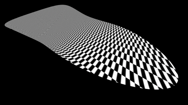
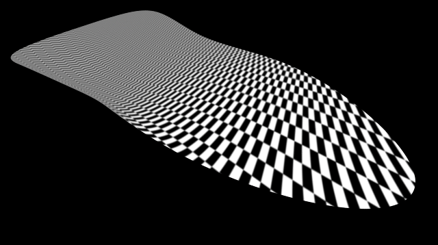
High frequency checker board textured on a large Loop surface using the standard four point s,t derivatives method (above) and the new filterregion method (below).
The Advantages of Filter Regions
The first issue that the filter region approach addresses is a limitation of the derivative-based approach. Derivatives are taken with respect to the parameterization of the surface. On Loop subdivision surfaces this parameterization changes discontinuously at face boundaries. This means that the derivative values will also change discontinuously at face boundaries. These discontinuities show up as changes in the amount of blur between faces. The problem is that we shouldn't determine our four points based on the parameterization of the surface, rather, we should be determining them based on how the texture coordinates vary over a shading-rate-determined region around the vertex. This is what a filterregion represents.
The next issue that the filter region approach addresses is that PRMan is conservative in how it treats the four points it is given for most filters. This conservative approach means that the amount of blurring that is actually done is based on how the region to be filtered over is oriented in texture space. In practice, this means that the amount of blurring can vary significantly based on the orientation of the surface and the transforms on the texture coordinates. This results in textures either appearing blurrier than they should or, occasionally, aliasing when they shouldn't. While the "ewa" filter tries to address some of these problems, it can't do as good a job as is possible because of the four point interface and the derivative issues.
While there are RSL solutions to both of the above problems, they can be expensive and complicated to use and maintain. The filter region approach is meant to simplify the usage and achieve as much performance as possible.
A filterregion works for 1D, 2D, or 3D texture coordinates on surfaces (including points and curves) as well as volumes. The usage patterns are exactly the same for each case.
Filter Region Functionality
It is easiest to think about a filterregion as a struct with methods. The workflow is to construct a filterregion, possibly modify it, possibly query it, and usually pass it to a shadeop that will filter over the region.
Methods for Creating Filter Regions
The easiest way to initialize a filterregion is to call one of the calculate methods on it:
void calculate1d(float s);
void calculate2d(float s,float t);
void calculate3d(triple V);
These functions construct a region that describes how the 1D, 2D, or 3D texture coordinates vary around the vertex. Sometimes the region to be filtered over is determined by properties other than just the local variation in the texture coordinates. In these cases, the filterregion can be constructed directly, by specifying the texture coordinates and two "axes" that describe the orientation and size of the region. The axes do not have to be orthogonal.
void calculate2d(float s,float t,
                 float axis0s, float axis0t, float axis1s, float axis1t);
void calculate3d(triple V, triple axis0, triple axis1);
For example, to construct a filterregion that will describe the cone around some reflection vector R, defined as R + a*T0 + b*T1 where a^2 + b^2 < 1, do the following:
fr->calculate3d(R,T0,T1);
Sometimes you may need to specify a filterregion directly, but want to make sure it is always large enough that it does not alias. That can be done with the extend method.
void extend(float axis0s, float axis0t, float axis1s, float axis1t);
void extend(triple axis0, triple axis1);
void extend(filterregion fr1);
extend makes sure the resulting filterregion bounds both of the specified regions. Note that the last call takes a filterregion as an arguement. The size and orientation of the argument are used to extend the calling region, while the actual texture coordinates are ignored.
In the reflection example above, this would be:
fr->calculate3d(R);
fr->extend(T0,T1);
Methods for Modifying and Querying Filter Regions
void scale(float amt)
void blur(float amt)
void clampaspectratio(float minaspect)
void maxsize()
void minsize()
There are a few ways to modify a filterregion. In practice, filtering is a bit of an art as well as a science. Sometimes a little more filtering is needed, sometimes a little less. scale(float amt) will scale the filterregion by amt. This is equivalent to the "width" optional argument to the texture ops.
Sometimes instead of scaling, you may need to add a fixed amount of blur to every lookup. This can be done with blur(float amt). This is almost the same as pre-blurring the function that is being filtered, and is equivalent to the "blur" optional argument to the texture ops.
Sometimes the filterregion describes a very long, narrow region in texture space. These long, narrow regions are often hard to sample efficiently and well. clampaspectratio(float minRatio) will clamp the ratio of the shorter axis to the longer axis to be above the specified minRatio.
The length of the longest axis can be queried with maxsize() and the length of the shortest axis can be queried with minsize(). One use for the maxsize is with a function like wnoise that takes a single filter width as an argument. For example:
filterregion fr;
fr->calculate3d(P);
wnoise(P, fr->maxsize());
Similarly, filtering a 1D delta function centered at zero with a triangle filter could be written:
filterregion fr;
fr->calculate1d(x);
float radius = fr->maxsize() / 2;
val = max(1 - abs(x)/radius, 0)
Functions Accepting Filter Regions
As of version 15, the following functions accept a filterregion as an argument.
- texture(string name; filterregion fr; [parameterlist])
- ptexture(string name; float channel, faceindex; filterregion fr; [parameterlist])
- shadow(string name; filterregion fr; [parameterlist])
- environment(string name; filterregion fr; [parameterlist])
- gather(string category; point P; filterregion fr; float numSamples; [parameterlist])
Putting It All Together
The following example uses a simple RIB file and two shaders to produce this image:
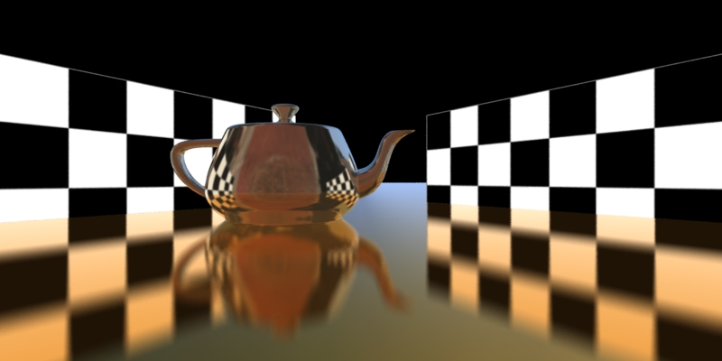
The first shader uses a filterregion to sample a texture. The amount of filtering is controlled by calling the scale method. The clampaspectratio method is used to prevent the region from becoming too long and narrow. This doesn't happen much in this scene.
surface surfテクスチャ(uniform float blurScale = 1)
{
   float ss =   s;
   float tt =   .25 * t;

   filterregion filt;
   filt->calculate2d(ss, tt);
   filt->scale(blurScale);
   filt->clampaspectratio(.1);

   Ci = texture("bigcheck_t", filt, "filter", "gaussian");
   Oi = 1;
}
The next shader is a simple metallic reflection shader. It determines the reflection direction and two vectors perpendicular to the reflection direction with different length will define the cone over which we want to sample. We will use these three vectors to explicitly construct a filterregion and use it in a gather loop. The result will be reflections that blur anisotropically, getting narrower nearer to grazing angle as many real surfaces. If the rays don't hit any geometry we will sample an env map, using a filterregion constructed from the ray direction to make sure we are filtering that lookup appropriately.
One thing to notice in this shader is that a filterregion constructed from direction vectors and normals should be done on normalized vectors, otherwise variations in the lengths of the vector can distort the result in undesirable ways. This is true for taking derivatives of direction vectors and normals as well.
class metal()
{
   public void ReflFrame(vector In; vector Nn; float coneSize;
                         output vector Rn, T0, T1)
   {
       // In points into the surface
       // Rn points out of the surface
       // compute Rn
       Rn = In - 2 * (In.Nn)*Nn;
       // T1 is perpendicular to Rn and Nn
       T1 = normalize(Rn ^ Nn);
       // T0 is in the plane of Rn and Nn and perpendicular to Rn
       T0 = normalize(Rn ^ T1);
       // scale T0n to coneSize
       T0 *= coneSize;
       // to account for half angle brdf and physical behavior, scale
       // T1n by Nn.Rn to narrow the reflection cone near grazing angle
       T1 *= coneSize * Nn.Rn;
   }

   private color GatherRefl(point P; vector Rn; vector T0; vector T1)
   {
       color ret = 0;
       color Cret = 0;
       vector rdir=0;
       uniform float raydepth;
       rayinfo("depth", raydepth);
       uniform float numSamps = (raydepth < 1)?  100 : 1;

       filterregion fr;
       fr->calculate3d(Rn, T0, T1);

       gather("illuminance", P, fr, numSamps, "surface:Ci", Cret, "ray:direction",rdir) {
           ret += Cret;
       } else {
           filterregion frEnv;
           frEnv->calculate3d(normalize(rdir));
           ret += environment("street.env", frEnv);
       }
       return ret / numSamps;
   }

   private color FrnlBlend(color vNormal; color vGrazing; float cosTheta)
   {   // Schlick's approximation to Fresnel
       float wt = pow(1 - cosTheta,5);
       return mix(vNormal, vGrazing, color(wt));
   }

   public void surface(output color Ci, Oi) {
       vector Nn = normalize(N);
       Ci = .15 * Cs;
       vector In = normalize(I);
       vector Rn, T0, T1;
       float coneSize = .035;
       ReflFrame(In, Nn, coneSize, Rn, T0, T1);
       color rho = FrnlBlend(Cs, color(1), abs(In.Nn));
       Ci += rho * GatherRefl(P, Rn, T0, T1);
       Oi = 1;
   }
}
The RIB file puts all the pieces together in a simple scene.
##RenderMan RIB
version 3.03

FrameBegin 1
Format 800 400 1

Display "reflection.tif" "it" "rgba"

Projection "perspective" "fov" [45]
Translate 0 -.5 0

WorldBegin
Attribute "visibility" "int diffuse" [1] "int specular" [1]

AttributeBegin
Surface "metal"

カラー .8 .5 .15
Patch "bilinear" "P" [ -80  0 100
                       80  0 100
                      -80  0 0
                       80  0 0]
Translate -1 0 5.75
Rotate -90 1 0 0
Scale .5 .5 .5
カラー .8 .75 .65
ジオメトリ "teapot"

AttributeEnd

Surface "surfテクスチャ"
AttributeBegin
Translate -3.5 0 0
Patch "bilinear" "P" [ -2  2 3
                       2  2 10
                      -2  0 3
                       2  0 10]
AttributeEnd

AttributeBegin
Translate 3.5 0 0
Patch "bilinear" "P" [ -2  2 10
                       2  2 3
                      -2  0 10
                       2  0 3]
AttributeEnd

WorldEnd
FrameEnd
Current Limitations
- The "lagrangian" filter for the texture shadeop is unsupported. It falls back to "gaussian".
- The environment shadeop with regular cube textures has problems with large filter sizes and edges that using a filterregion doesn't solve. We recommend using txmake -penvcube to create a ptexture environment map so that better filtering can be done over the edges.