Using the Subdivision Mesh Primitive
Using the Subdivision Mesh Primitive
August, 1998
Currently, the most common way to model complex smooth surfaces is by using a patchwork of trimmed NURBS. Trimmed NURBs are used primarily because they are readily available in existing commercial systems. They do, however, suffer from at least two difficulties:
- Trimming is expensive and prone to numerical error.
- It is difficult to maintain smoothness, or even approximate smoothness, at the seams of the patchwork as the model is animated.
Subdivision surfaces overcome both of these problems: they do not require trimming, and smoothness of the model is automatically guaranteed, even as the model animates.
A subdivision surface, like a parametric surface, is described by its control mesh of points. The surface itself can approximate or interpolate this control mesh while being piecewise smooth. Furthermore, its control mesh is not confined to be rectangular, which is a major limitation of NURBs and uniform B-splines. In this respect, the control mesh is analogous to a polygonal description. But where polygonal surfaces require large numbers of data points to approximate being smooth, a subdivision surface is smooth - meaning that polygonal artifacts are never present, no matter how the surface animates or how closely it is viewed.
The basic idea is to construct a surface from an arbitrary polyhedron by an appropriate repeated subdivision of each of the faces, as illustrated in Figure 1. This subdivision process eventually converges to a smooth surface that is commonly called the limit surface (which is the result of rendering).
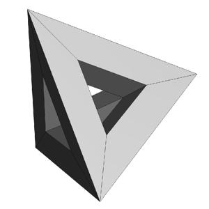
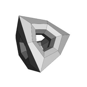
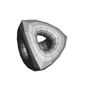
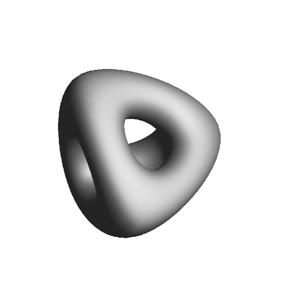
Fig.1 Recursive subdivision of a polyhedron. The control mesh is at the top left.
Following in left to right order, are the mesh after one subdivision step,
two subdivision steps, and the limit surface.
As subdivision surfaces go, there are a number of species to choose from, but all subdivision surfaces have this recursive subdivision property. PRMan currently implements one such subdivision scheme called the Catmull-Clark scheme. Whereas other schemes subdivide into triangles or interpolate their control points, the Catmull-Clark scheme produces quadrilaterals and approximates their points. We prefer Catmull-Clark surfaces for the following reasons:
- Quadrilaterals are often better than triangles at capturing the symmetries of naturally occuring objects, e.g. arms, legs, and surfaces of revolution, and
- Catmull-Clark surfaces strictly generalize uniform bicubic B-splines; that is, a region of the Catmull-Clark surface represented by a rectangular mesh of points is exactly equivalent to the corresponding uniform bicubic B-spline. Using this knowledge, you can, with some care, craft together a patchwork of surfaces mixing Catmull-Clarks and B-splines, and have them join together seamlessly.
It is possible to modify the subdivision rules to create piecewise smooth surfaces containing infinitely sharp features such as creases and corners (Fig. 4). As a special case, surfaces can be made to interpolate their boundaries by tagging their boundary edges as sharp (Fig. 5).
However, we've recognized that real world surfaces never really have infinitely sharp edges, especially when viewed sufficiently close. To this end, we've added the notion of semi-sharp creases, i.e. rounded creases of controllable sharpness (Fig. 3). These allow you to create features that are more akin to fillets and blends. In PRMan, as you tag edges and edge chains as creases, you also supply a sharpness value that ranges from 0-10, with sharpness values >=10 treated as infinitely sharp.
It should be noted that infinitely sharp creases are really tangent discontinuities in the surface, implying that the geometric normals are also discontinuous there. Therefore, displacing along the normal will likely tear apart the surface along the crease. If you really want to displace a surface at a crease, it may be better to make the crease semi-sharp.
サンプル
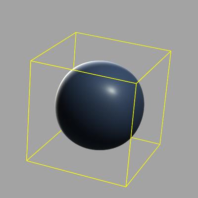
A simple closed, smooth surface:
SubdivisionMesh "catmull-clark"
[4 4 4 4 4 4] [0 2 3 1 4 6 7 5 5 1 3 4 2 0 7 6 6 4 3 2 1 5 7 0]
"P" [ 25 -25 -25 25 25 -25 25 -25 25 25 25 25-25 25 25 -25 25 -25 -25 -25 25 -25 -25 -25]
Fig. 2 Simple surface with control mesh in yellow.
An example with semi-sharp creases:
SubdivisionMesh "catmull-clark"
[4 4 4 4 4 4] [0 2 3 1 4 6 7 5 5 1 3 4 2 0 7 6 6 4 3 2 1 5 7 0]
["crease" "crease"] [5 1 5 1] [1 5 7 0 1 3 4 6 2 3] [2 2]
"P" [ 25 -25 -25 25 25 -25 25 -25 25 25 25 25 -25 25 25 -25 25 -25 -25 -25 25 -25 -25 -25]
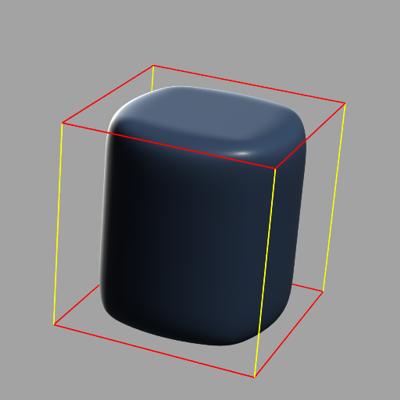
Fig. 3 Surface with semi-sharp creases (in red) set to 2.
SubdivisionMesh "catmull-clark"
[4 4 4 4 4 4] [0 2 3 1 4 6 7 5 5 1 3 4 2 0 7 6 6 4 3 2 1 5 7 0]
["crease" "crease"] [5 1 5 1] [1 5 7 0 1 3 4 6 2 3] [10 10]
"P" [ 25 -25 -25 25 25 -25 25 -25 25 25 25 25 -25 25 25 -25 25 -25 -25 -25 25 -25 -25 -25]
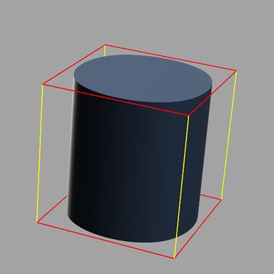
Fig. 4 Surface with infinitely sharp creases (in red).
Interpolating the mesh boundaries:
SubdivisionMesh "catmull-clark"
[4 4 4 4 4 4 4 4 4]
[0 4 5 1 1 5 6 2 2 6 7 3 4 8 9 5 5 9 10 6 6 10 11 7 8 12 13 9 9 13 14 10 10 14 15 11]
["interpolateboundary"] [0 0] [] []
"P" [-60 60 0 -60 20 0 -60 -20 0 -60 -60 0 -20 60 0 -20 20 45 -20 -20 45 -20 -60 0 20 60 0 20 20 45 20 -20 45 20 -60 0 60 60 0 60 20 0 60 -20 0 60 -60 0]
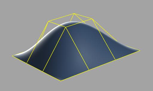
Fig. 5 Open surface that interpolates boundaries.
As far as texture mapping goes, you might suspect that for a subdivision surface, there is no global st-space. Normally, we can use projection techniques and "paint" textures directly onto the surface. Subdivision surfaces, like other PRMan geometric primitives, allow users to associate Pref data with vertices so that projected textures can be handled properly.
In construction a subdivision mesh, special attention must be paid to its topology so that it subdivides correctly. Some important rules to observe are:
- Edges intersect only at their end points.
- Each edge must be adjacent to either one or two faces; if one, then it is a boundary edge.
- Each vertex must be adjacent to at least two edges, i.e. there are no "dangling" vertices.
- A vertex is uniquely referenced through its index, i.e. references to two points that have the same geometric coordinates do not constitute references to the same vertex.
Portions of this Applications Note originally appeared in:
Tony DeRose, Michael Kass, Tien Truong, "Subdivision Surfaces in Character Animation," SIGGRAPH '98 Proceedings, Orlando, FL, July 20, 1998.