The Viewing Transformation
The Viewing Transformation
July, 1990
Perhaps one of the least understood sections of the RenderMan Interface Specification is the viewing transformation. Hidden among the calls to RiScreenWindow, RiFrameAspectRatio and others are the keys to getting your intended camera view onto the pixels of a display device. This note will try to demystify this large group of RenderMan procedures and their parameters, so that you can reliably generate the image you want without distress.
The viewing transformation converts objects from their 3-dimensional camera-space coordinates into the appropriate 2-dimensional raster-space coordinates. The camera coordinate system is a coordinate system with the camera at the origin, looking out over the positive z axis. It is, essentially, the scene from the camera's point of view. The raster coordinate system is the space of the pixels on the monitor. Connecting these two coordinate systems there is a special coordinate system known as the screen coordinate system. The screen coordinate system is, conceptually, the same as the film plane of a camera. It is usually best to consider both the screen coordinate system and the raster coordinate system to be two-dimensional, even though we know that RenderMan can output depth information.
The RenderMan Interface Specification has a rather complex viewing transformation. The interface has many calls which each set-up a small piece of the transformation. Each of these values has a “reasonable” default, which is to say that if you don't set it, it will default to something which is probably appropriate, given the values that you have already set. What is confusing about all of this is that in order to be “appropriate given what you have already set”, these defaults are interrelated in complex ways. The good news is that this means you typically only need to set some of the values in order to get the picture you want. The bad news is that if you are trying to understand the whole pipeline, it is quite involved. Hopefully this application note will clarify these relationships. This material is presented in a different form in Chapter 8 of The RenderMan Companion, and the reader might want to read both treatments before deciding that he understands this topic.
THE SIMPLEST CASE
The simplest case is to let absolutely everything default. This is possible using RenderMan, and the image you get is entirely reasonable. Consider the following program:
static RtPoint vertices[3] = {
	{-.5,.5,1.0}, {.5,.5,1.0}, {0,0,1}     /* triangle at z=1 */
};
RiBegin(RI_NULL);
RiWorldBegin();
RiPolygon(3, RI_P, (RtPointer)&vertices, RI_NULL);
RiWorldEnd();
RiEnd();
Using PhotoRealistic RenderMan this program would generate a TIFF image of the triangle, named ri.pic, at a resolution of 512x384. The camera is at the origin of the world coordinate system, which is the same coordinate system as the triangle is in, so the triangle one unit in front of the camera. It is an orthographic projection, and since the image resolution is 4/3 as wide as it is tall, we can see everything in the scene that falls inside the box from x = -4/3 to x = +4/3 and from y = -1 to y = +1. The third vertex of the triangle, which is at the (x,y) origin, is in the center of the image.
In practice, one or more of those values is probably not quite what you want for your application. The procedures described below change those values from their defaults to specific desired values, and, as mentioned above, such changes sometimes change the defaults of other values as well.
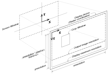
Figure 1. Screen-to-raster geometry

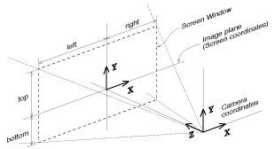
Figure 2. カメラ-to-screen geometry

SCREEN-TO-RASTER PROCEDURES
The viewing transformation can be broken down into two pieces, the camera-to-screen projection and the screen-to-raster projection. The camera-to-screen projection flattens the 3-D world onto the 2-D screen. The screen-to-raster projection maps every point on the screen onto some output pixel. In the next section, we will see how we can specify a rectangle of interest on the screen. In this section, we will discuss the screen-to-raster projection, whose job it is to figure out how to get that screen rectangle onto the raster.
Resolution
The first, and most obvious thing you might want to change is the image resolution. The default for resolution is determined by the output device. Each output device has a default resolution, and the default output device, a TIFF image, has a default resolution of 512 by 384. By using the RiDisplay call, you can change the output device, and this will determine the new default resolution. If you want strict control of the resolution, the RiFormat call can be used to set an explicit output resolution. It should be made clear that the resolution values given by RiDisplay and RiFormat are device maximum resolutions. No image may be made bigger than this resolution. It might happen that a smaller image would be made, as we will see later.
Pixel Aspect Ratio
Another thing that RiDisplay and RiFormat change is the pixel aspect ratio. Pixel aspect ratio defines the ratio of the width to the height of the individual pixels on the device. Many displays have square pixels, and the ratio is 1.0; other displays have pixels that are wider than they are tall, or vice-versa. The TIFF default for pixel aspect ratio is 1.0, and each framebuffer device has the correct default for its monitor. It is rare to need to change this value, but if you do (for example, you are rendering on one device for later display on another) it is done with RiFormat. If you want to use RiFormat to set the resolution, but don't want to change the pixel aspect ratio (or vice-versa), use a value less than or equal to 0.0 for the RiFormat argument you don't want to modify. It will then retain its default value.
Frame Aspect Ratio
The other aspect ratio which is available in RenderMan is the frame aspect ratio. This is used to force the exact ratio of the width to the height (shape) for the output image as a whole. For example, you may have heard that NTSC video “has a 4 to 3 aspect ratio”, or that 70mm film “has a 1.85 aspect ratio”. You can set the required frame aspect ratio with RiFrameAspectRatio. If you do not set it, it defaults to the full size of the output device, which is usually what you want.
It should be obvious that the combination of resolution and pixel aspect ratio already define what the frame aspect ratio is, and that specifying it again is either redundant or inconsistent. So why is it in the interface? If you know specifically what ratio you need, then you always want exactly that ratio, independent of what resolution or pixel aspect ratio you are using. In particular, you can make your rendering requests device-independent by specifying only the frame aspect ratio. Then the device can set the “default” (but actually “device maximum”) resolution and pixel aspect ratio, and your image will use the appropriate subset of that, in order to make the largest image possible which still has the correct frame aspect ratio.
What if you redundantly set both format and frame aspect ratio? You get the biggest image of the correct shape smaller than your specified format. Notice that if you let the pixel aspect ratio default, then frame aspect ratio is not really redundant, because going to a different device with a different pixel aspect ratio will give you a differently shaped image even though it has the same resolution.
Crop Windows
Sometimes you want to generate only a small part of an image rather than render the whole thing. You could move the camera, zoom in on the section you wanted, and adjust the resolution, but that would be pretty complicated. Instead, it is very easily done with RiCropWindow. Setting a crop window does not change anything about the camera placement or viewing parameters. The only thing it does is indicate which subset of the normal output pixels you actually want rendered to the device. The crop window is specified as a fraction of the total image, rather than in pixel numbers, so that it is a resolution-independent value. The default is obviously 0.0 through 1.0 in both x and y.
CAMERA-TO-SCREEN PROCEDURES
The screen coordinate system is, conceptually, the same as the film plane of a camera. Just as the lens of the camera focuses the light onto the film plane, so the camera-to-screen transformation projects the objects in the scene into screen coordinates. Note that the screen coordinate system is not the film itself, but the unbounded two-dimensional plane that the film lies on. The design of a real camera can choose how big the film is and how it is centered on the film plane, and even whether the film plane is perpendicular to the lens system. The camera-to-screen transformation controls all of these parameters in RenderMan's virtual camera.
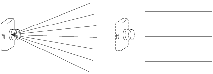
Figure 3. Perspective versus orthographic projections

Projections
The first step in the camera-to-screen transformation is to set up the camera projection. There are two kinds of projections available in PhotoRealistic RenderMan: orthographic and perspective. The projection is set by the RiProjection procedure, and defaults to an orthographic projection.
A perspective projection is the kind we are normally used to, with a vanishing point at the horizon, and where objects shrink as they get farther away. Typically, we think of looking through the top of a pyramid, with the tip at the camera point, and the screen (film) plane exactly one unit in front of the camera. Objects are projected onto the screen plane along lines that intersect at the camera and get farther apart with distance.
An orthographic projection is a much simpler projection. This is sometimes called a “parallel projection”, because here we project objects onto the screen plane along parallel lines that are perpendicular to the screen. They don't go through the camera at all, unless you like to think of the camera as being an infinite distance behind the screen plane. Objects appear the same size on the screen independent of their distance from the camera.
Screen Window
It should be clear that we can draw such projection lines to any object which is in front of the camera, and thus all objects project to the screen somewhere. However, we don't want everything to be in the image, so we only display those objects which project into a certain rectangle of interest on the screen, the so-called screen window. You can think of the screen window as being the rectangle which is the intersection of the perspective viewing pyramid or orthographic viewing box with the screen plane. It is this rectangle which is then projected onto the display device by the screen-to-raster transformation.
The screen window is set by the RiScreenWindow procedure. Generally, the screen window is centered at the origin. That way, objects right in front of the camera appear in the middle of the output image. Also, generally, the screen window has the same shape (frame aspect ratio) as the display device. If this were not true, shapes of objects in the world would be distorted when they appeared in the image. The default for screen window obeys both of these conventions. It is centered around the origin, and its shape is set to be the same as the frame aspect ratio. Its overall size is chosen so that it ranges from -1 to 1 in the smallest direction. So, if the frame aspect ratio is wider than tall, the default will be -1 to 1 in y, and wider than that in x. If the frame aspect ratio is taller than it is wide, the default will be -1 to 1 in x, and taller than that in y.
The screen window can be used to zoom in or out. Shrinking the screen window (keeping the same shape) is equivalent to shrinking the viewing pyramid, and this means a smaller section of the world will get projected onto the same raster: a zoom. The screen window can also be used to create off-center projections, by merely specifying a window that is not symmetric about the origin. And, as mentioned above, if the screen window is not the same shape as the frame aspect ratio, you get an image which appears stretched in one direction (anamorphic), like the ones you get with a Panavision camera lens. Offset screen windows can also be used to present stereographic images.
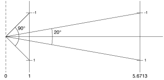
Figure 4. Field of view geometry

Field of View
The perspective projection can take one optional argument which is the field of view. This parameter is very similar to the screen window, and is therefore a bit confusing. The perspective field of view moves the screen plane toward or away from the camera, so that the square which falls between (-1,1,-1,1) in screen coordinates covers the specified angle, as seen from the camera. For example, by default the field of view is 90 degrees, and thanks to trigonometry this means the screen plane is 1.0 units in front of the camera. If you were to specify a field of view of 20 degrees, the screen plane would be moved back to 5.6713 units away (1.0/tan(10.0)).
It is popular to use only the field of view to control the viewing pyramid, in a way similar to the way a physical camera is used. In this scheme, the screen window is allowed to default to its normal value of (-1,1) in the “smaller” direction, and the field of view controls how much is visible through this screen window. The field of view control can then be thought of as the minimum of the horizontal or vertical field of view, because in the “larger” direction you see an even wider angle. This scheme is not as general as using RiScreenWindow, since it gives you only undistorted centered perspective views, but this is usually what you want, anyway.
It can be very confusing if you try to use both field of view and screen window at the same time. Remember, the field of view does not specify the viewing angle through the specified screen window -- it specifies the viewing angle through the (-1,1,-1,1) window by moving the screen plane. The screen window is then figured relative to this moved screen plane, and you get double motion. In practice, this is pretty hard to control, and is only used in rare circumstances.
Screen Transforms
The RenderMan Interface Specification describes the concept of a screen transformation, which is saved when RiProjection is called. This is a matrix which is applied to objects after the projection onto the screen and field-of-view calculation, but before the screen windowing occurs. This matrix would model effects such as plan views, where the film plane is not perpendicular to the lens. However, PhotoRealistic RenderMan does not support the use of a post-projection transformation in this way. The only screen transform which PhotoRealistic RenderMan can support is a scale or translation in the 2-D coordinates of the screen plane. This makes the screen transform no more powerful than RiScreenWindow, and as a result, it is not used very often.
CONCLUSION
The viewing transformation has lots of controls, but typically they are not all used together. Rather, a couple important controls are set and the rest are let to default to their “logical” values. So, even though the RenderMan Interface Specification is confusing when it describes all of the complex interactions of the controls, this need not be a burden to the average user. He just needs to remember a few simple rules:
The device knows its maximum resolution and pixel aspect ratio, and these can be overridden with RiFormat.
The chosen resolution and pixel aspect ratio determine the frame aspect ratio, and this can be overridden with RiFrameAspectRatio. If you override this, you won't use all of the pixels on the device.
The frame aspect ratio determines the default screen window, which is centered and encloses the -1 to +1 square. This can be overridden by RiScreenWindow to zoom or to provide off-center or anamorphic views.
Zooming can also be done by using RiProjection ("perspective", "fov", ...) to set the minimum of the horizontal or vertical field-of-view. The other will be appropriate to meet the frame aspect ratio. It is best not to use this and RiScreenWindow at the same time.
With these rules in mind, it should be easy to get exactly the view you want onto exactly the pixels you want.
